The mascot nuonuo is raising its thumb.
Electromagnetic Solenoid Dosing Pump Installation

Electromagnetic Solenoid Dosing Pump Installation Guide

Installation & Precautions

During the installation process of an electromagnetic solenoid dosing pump, it is important to follow specific installation guidelines and avoid situations that may hinder its proper functioning. Accurate and error-free installation process can make the dosing pump put into operation quickly and improve its production efficiency. While an incorrect installation may cause unnecessary cost losses. We have compiled a perfect installation process for your reference. You may use it as a guide during the installation.

Electromagnetic solenoid dosing pump and various accessories
  1. Installation site: The place where the dosing pump is installed should be dry, far away from heat sources, and the ambient temperature should not exceed 0–40 °C.
  2. Installation method: When installing dosing pumps, the following situations will usually be encountered.
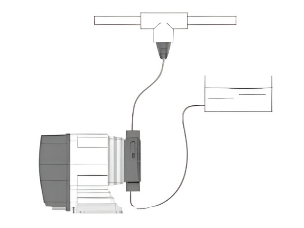
    a The installation position of the dosing pump is lower than the liquid level in the dosing tank, and the position of the dosing point is higher than the liquid level in the dosing tank. This is an ideal installation mode. In this case, the liquid can flow directly into the pump head of the dosing pump, emptying the air in the dosing pump, and the dosing pump can be started easily. This installation method is recommended for liquids that easily generate bubbles, such as sodium hypochlorite, hydrogen peroxide, or liquids with high viscosity.
    The electromagnetic solenoid dosing pump is lower than the liquid level of dosing box.
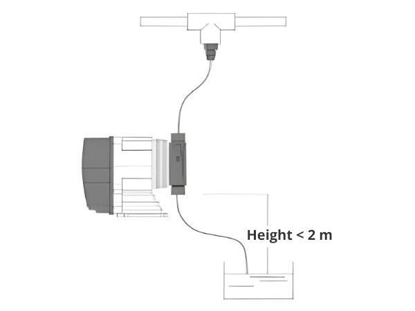
    b The installation position of the dosing pump is higher than the liquid level in the dosing tank, but lower than the position of the dosing point. For this installation method, attention should be paid to the height difference between the pump head and liquid level of the dosing pump. This value is related to the suction distance of the dosing pump. The suction distance of DFD, DP, DM and DC series dosing pumps are 2m. If the height difference between the pump head and the liquid medicine is greater than 2m, the dosing pump will not work normally. Therefore, when installing the dosing pump, the height difference between the two (i.e. the suction line) should be shortened as far as possible.
    The electromagnetic solenoid dosing pump is higher than the liquid level of dosing tank.
    c The liquid level in the dosing tank is higher than that of the dosing point. When the dosing pump is installed in such a situation, siphon phenomenon will occur between the dosing tank and the dosing point. Even if the dosing pump stops working, the liquid will flow directly from the dosing tank to the dosing point. If this happens, install a back pressure valve on the outlet line of the dosing pump to adjust the magnitude of back pressure until the above situation does not occur.
    Electromagnetic solenoid dosing pump, dosing tank and dosing point liquid level

    Notes:

    • Avoid sharp bends and knot in the inlet and outlet pipes and do not make the pipes be scratched or cut off by sharp edges and corners.
    • The screw thread size at the one-way valve of the D series electromagnetic solenoid dosing pump is G 1/2 straight pipe thread. Even if the raw material belt is wrapped, leakage will occur with the passage of time. If the liquid is highly corrosive, it will have a greater impact on the dosing pump.
    • It is strictly prohibited to directly connect with the G 1/2 female threaded connector after wrapping the raw material tape at the pump head inlet and outlet.
  3. Electrical Wiring

    The electromagnetic pump is equipped with a 1.5m random cable, which can be extended by the user or supplied by the manufacturer. During electrical installation, an air switch should be installed between the pump and the power supply. The installation should comply with the local electrical installation regulations. Note: Make sure that the power supply circuit is disconnected during wiring.

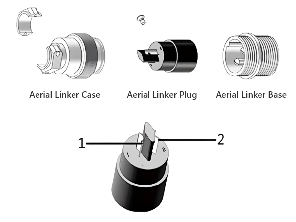
    When connecting signal wires, refer to the following diagram for wiring, and note that there are corresponding terminal numbers under the solder wire terminals.

    Many accessories for electromagnetic solenoid dosing pump electrical connection

    Incorrect wiring can cause irreversible damage to the dosing pump, please read the following carefully.

  4. Control Wiring
    DFD The DFD dosing pump only has a remote control interface.
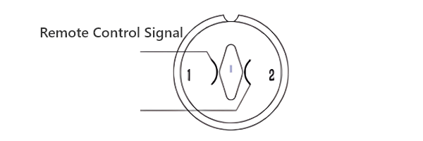
    Remote control interface: The signal is the switching signal of the dry node, normally on or off control.
    DFD dosing pump remote control interface diagram
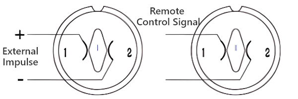
    DP The DP dosing pump has two interfaces: remote control interface and pulse control interface.
    Remote control interface: The interface signal is the switch signal of the dry node, normally on or off control;
    Pulse control interface: The interface signal is pulse signal or passive switch signal. The generated pulse signal voltage cannot exceed 24V. The dosing pump automatically adjusts the output flow rate of the dosing pump according to the change of the external pulse signal.
    DP dosing pump remote control interface and impulse control interface diagram
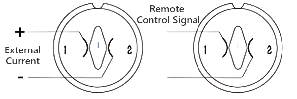
    DM The DM dosing pump has two interfaces: remote control interface and current control interface.
    Remote control interface: The interface signal is the switch signal of the dry node, normally on or off control;
    Current control interface: The interface signal is the standard current signal 0/4–20 mA, and the dosing pump automatically adjusts the output flow rate of the dosing pump according to the change of the external current signal. The control mode is proportional control, and the proportional coefficient can be adjusted to realize frequency division and frequency multiplication.
    DM dosing pump remote control interface and current control interface diagram
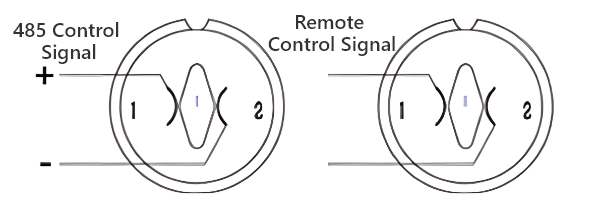
    DC The DC dosing pump has two interfaces: remote control interface and 485 control interface.
    Remote control interface: The interface signal is the switch signal of the dry node, normally on or off control;
    485 control interface: The dosing pump automatically adjusts the output flow rate of the dosing pump according to the change of the external 485 signal (free communication protocol, non-mOdbus and Profibus).
    DC dosing pump remote control interface and current control interface diagram

    Notes:

    It is strictly prohibited to connect the positive and negative signal lines in reverse, otherwise, it will cause damage to the circuit board or damage to the entire pump.

  5. Pipeline Connection

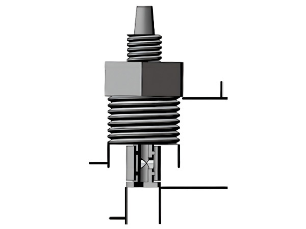
    Standard DFD, DP, DM and DC dosing pumps come with a 2 m PVC transparent liquid inlet hose, a 1.5 m PE translucent liquid outlet hose, a filter (PP) and a sprayer (PP). One end of the inlet pipe is connected with the filter and the other end is connected with the inlet check valve of the dosing pump; One end of the liquid outlet pipe is connected with the outlet check valve of the dosing pump and the other end is connected with the sprayer. The thread of sprayer is G 1/2 (4 scruples), which can be directly screwed into other pipe valve parts by wrapping the raw material tape.

    Electromagnetic solenoid dosing pump pipeline connection

    Operation Warning

    • Do not allow the pump to run with the outlet line completely closed. Otherwise, it may cause liquid leakage or pipe rupture. Therefore, please ensure that the valve of the outlet pipeline is fully opened before opening the dosing pump.
    • Do not allow the dosing pump working without liquids for a long time. Although idling the pump will not cause damage to the diaphragm or burn the pump, repeated or prolonged idling will cause the temperature of the dosing pump to rise, accelerating the aging of electrical components and electromagnets and reducing the service life of the dosing pump.
  6. Inspection & Maintenance
    • Install a section of pipe on the exhaust valve to return the dosing tank or other collecting container.
    • Check the pre-tightening torque of the pump head bolts regularly to keep its firmly connected with pump body. If the pump head connecting bolt is loose, the pump head will be easy get leakage. The specified bolt pre-tightening torques are as shown below.
      • M/HX: 2.16 N.m
      • NX/GX: 2.41 N.m
      • 30L/50L: 2.90 N.m
    • Recommended regular inspection time: continuous operation for 500 hours or cumulative operation for 1000 hours.
  7. Liquid Suction

    Install the dosing pump according to the above requirements and start it. If the pump head is equipped with an exhaust valve, firstly, unscrew the exhaust valve by half a turn, the liquid will be sucked into the pump head very quickly. Then close the exhaust valve after the liquid starts to discharge from the exhaust valve.

    If the pump head is not provided with an exhaust valve, remove the discharge pipe from the injection valve at the dosing point. When the liquid medicine enters the discharge tube, turn off the pump and reconnect the pipe to the injection valve.

  8. Flow Regulation & Calibration

    If it is necessary to adjust or calibrate the flow rate of the dosing pump by yourself, the dosing pump shall be calibrated on site.

    • Place the foot valve in a container with scale and have a sufficient amount of clean water.
    • Start the pump, unscrew the exhaust valve and discharge air bubbles, tighten the screw, and stop the pump. Write down the scale A (mL) at this time.
    • Start the pump and start the timing to calculate a certain time T (min) (it is recommended not to be less than 5 min). Write down the scale B (mL) at this time.
    • The flow rate by this moment is
      The electromagnetic solenoid dosing pump flow rate calculation formula
    • Write down the current name displayed on the dosing pump panel, N1
    • The actual required flow rate is G(L/H).
    • The actual frequency number that dosing pump needs to adjust the panel is
      The electromagnetic solenoid dosing pump stroke frequency formula

You can install the dosing pump correctly according to the above tips, so that your dosing pump can be put into the work of conveying liquids as soon as possible. If you encounter problems that cannot be solved during the installation process, please feel free to contact us and we will try our best to help you solve these problems.