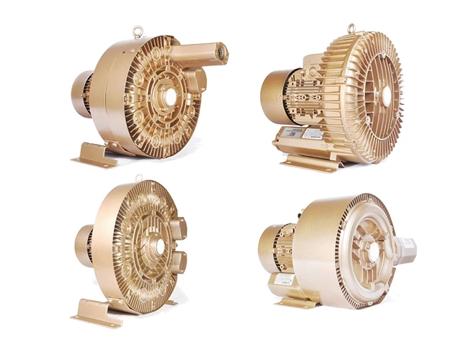
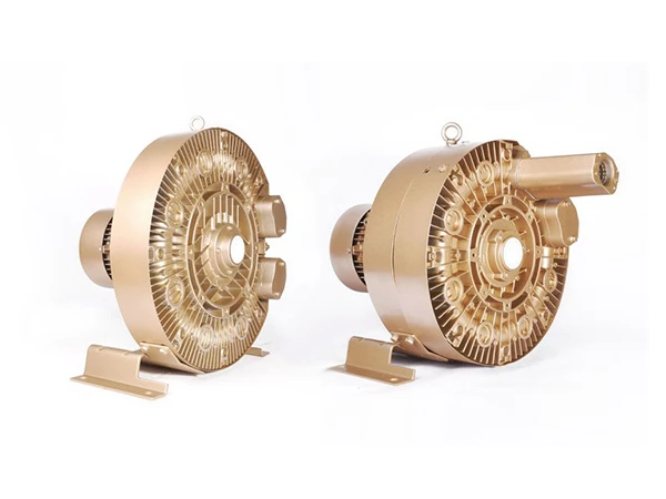
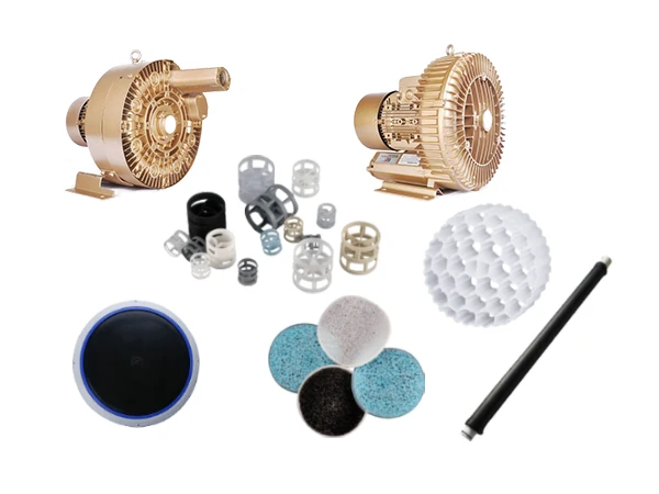
4 different types of regenerative blowers

Regenerative Blower – Efficient & Energy-Saving Air Delivery Equipment

Regenerative blowers, also known as side channel blowers or vortex blowers, are commonly used gas pressurization devices in applications such as water treatment, pneumatic conveying, and environmental protection equipment. Their design allows them to generate relatively high airflow pressure and low flow rates, making them particularly suitable for situations requiring stable air delivery over extended periods. Regenerative blowers differ from traditional centrifugal fans or Roots blowers by relying on the high-speed rotation of the impeller to generate vortices, compressing air through multiple cycles to achieve pressurization.

  • Specification
  • Working Principle
  • Video
Specification
  • 2 GHBH series high pressure regenerative blowers

    GHBH Series High Pressure Regenerative Blower

  • 2 GHBG series ultra high pressure regenerative blowers

    GHBG Series Ultra High Pressure Regenerative Blower

GHBH Series High Pressure Regenerative Blower

The GHBH series high-pressure regenerative blowers are efficient and reliable air delivery devices, primarily used in industrial applications requiring high pressure and high flow rates. This series of blowers employs advanced design and manufacturing processes, providing contactless, oil-free air flow delivery, suitable for various industrial needs such as gas transmission, vacuum suction, and wastewater treatment. When paired with a variable frequency drive, the performance of the GHBH series high-pressure regenerative blower can be significantly improved.

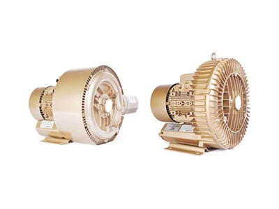
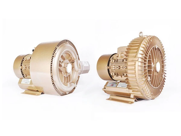
2 GHBH series high pressure regenerative blowers

Specification

Read MoreRead Less
Table 1: GHBH Series High Pressure Regenerative Blower Specification
Model Frequency Motor Weight Sound Max Airflow Max Vacuum Max Pressure Pressure Relief Valve/Filter
Rated
Power Voltage Current
Hz KW V A Kg Db (A) m³/h mbar mbar
GHBH 0D5 12 1R2 50 0.37 200–240 2.7 11 53 80 -110 110 RV-01/MF-10
60 0.45 220–275 3.0 56 98 -130 140 RV-01/MF-10
GHBH 0D5 12 AR2 50 0.37 200–240 2.7 11 54 100 -110 110 RV-01/MF-10
60 0.45 220–275 3.0 57 120 -130 140 RV-01/MF-10
GHBH 001 12 2R2 50 0.7 200–240 4.5 15 55 88 -210 240 RV-01/MF-10
60 0.83 220–275 5.6 61 103 -250 250 RV-01/MF-10
GHBH D73 12 1R3 50 0.55 200–240 3.7 13 55 100 -120 120 RV-01/MF-10
60 0.62 220–275 4.5 57 120 -130 150 RV-01/MF-10
GHBH 001 12 1R3 50 0.7 200–240 4.8 14 55 100 -150 150 RV-01/MF-10
60 0.8 220–275 4.1 57 120 -150 160 RV-01/MF-10
GHBH 1D7 12 2R3 50 1.1 200–240 7.3 17 58 120 -240 280 RV-01/MF-10
60 1.3 220–275 8.3 60 145 -230 260 RV-01/MF-10
GHBH 1D2 12 1R4 50 0.8 200–240 5.2 15 63 145 -150 160 RV-01/MF-12
60 0.9 220–275 5.8 64 175 -160 140 RV-01/MF-12
GHBH 1D7 12 1R4 50 1.1 200–240 7.3 16 63 145 -150 190 RV-01/MF-12
60 1.3 220–275 8.3 64 175 -180 190 RV-01/MF-12
GHBH 002 12 2R4 50 1.5 200–240 9.0 26 66 150 -280 290 RV-01/MF-12
60 1.75 220–275 10.0 69 180 -250 280 RV-01/MF-12
GHBH 1D2 12 AR4 50 0.85 200–240 5.2 16 64 180 -100 110 RV-01/MF-12
60 0.95 220–275 5.8 66 210 -100 110 RV-01/MF-12
GHBH 1D7 12 AR4 50 1.1 200–240 7.3 17 64 180 -170 210 RV-01/MF-12
60 1.3 220–275 8.3 66 210 -145 145 RV-01/MF-12
GHBH 1D7 12 1R5 50 1.1 200–240 7.3 21 64 210 -160 160 RV-01/MF-16
60 1.3 220–275 8.3 70 255 -150 160 RV-01/MF-16
GHBH 002 12 1R5 50 1.5 200–240 9.0 24 64 210 -190 200 RV-01/MF-16
60 1.75 220–275 10. 70 255 -180 180 RV-01/MF-16
GHBH 002 12 AR5 50 1.5 200–240 9.0 26 65 270 -140 120 RV-01/MF-16
60 1.75 220–275 10.0 71 330 -110 100 RV-01/MF-16
GHBH 003 12 1R7 50 2.2 200–240 12.8 30 72 318 -190 190 RV-01/MF-16
60 2.55 220–275 12.8 74 376 -190 200 RV-01/MF-16
Note: The motor is a single-phase motor.

GHBG Series Ultra High Pressure Regenerative Blower

The GHBG series ultra-high pressure regenerative blower can generate a pressure difference of up to 1,000 bar, enabling stable gas transportation over long distances or through complex piping networks. It can maintain efficient operation even when facing challenges such as system resistance, bends, or height differences. This series of blowers also features low noise and no wear characteristics, allowing for continuous operation for up to 20,000 hours without any maintenance or repairs.

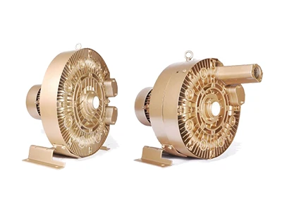
2 GHBG series ultra high pressure regenerative blowers

Specification

Read MoreRead Less
Table 2: GHBG Series Ultra High Pressure Regenerative Blower Specification
Model Frequency Motor Weight Sound Max Airflow Max Vacuum Max Pressure Pressure Relief Valve/Filter
Rated
Power Voltage Current
Hz KW V A Kg Db (A) m³/h mbar mbar
GHBG D73 12 1R2 50 0.55 200–240 3.1 18 57 47 -230 290 RVG1.2/MF-10
60 0.63 220–275 7.1 62 57 -270 320 RVG1.2/MF-10
GHBG 1D2 12 1R3 50 0.94 200–240 9.0 18 57 66 -250 350 RVG1.2/MF-10
60 1.1 220–275 9.0 62 80 -280 390 RVG1.2/MF-10
GHBG 1D7 12 1R4 50 1.1 200–240 10.1 23 55 87 -300 380 RVG1.2/MF-10
60 1.3 220–275 10.3 62 105 -350 390 RVG1.2/MF-10
GHBG D73 34 1R2 50 0.55 200–240 △/345–415 2.8 △/1.6Y 16 57 47 -230 290 RVG1.2/MF-10
60 0.63 220–275 △/380–480 3.0 △/1.7Y 62 57 -270 320 RVG1.2/MF-10
GHBG D73 34 1R3 50 0.55 200–240 △/345–415 2.8 △/1.6Y 16 57 66 -250 250 RVG1.2/MF-10
60 0.63 220–275 △/380–480 3.0 △/1.7Y 62 80 -260 250 BVG1.2/MF-10
GHBG 1D2 34 1R3 50 0.81 200–240 △/345–415 4.0 △/2.3Y 17 59 66 -280 350 RVG1.2/MF-10
60 0.94 220–275 △/380–480 4.0 △/2.3Y 62 80 -340 360 RVG1.2/MF-10
GHBG 1D7 34 1R4 50 1.1 200–240 △/345–415 5.4 △/3.1Y 23 55 87 -300 380 RVG1.2/MF-10
60 1.3 220–275 △/380–480 5.4 △/3.1Y 62 105 -340 370 RVG1.2/MF-10
GHBG 002 34 1R5 50 1.5 200–240 △/345–415 7.5 △/4.3Y 26 64 120 -310 360 RVG1.2/MF-10
60 1.75 220–275 △/380–480 7.6 △/4.4Y 68 145 -340 320 RVG1.2/MF-10
GHBG 003 34 1R5 50 2.2 200–240 △/345–415 11.4 △/6.6Y 29 64 120 -310 470 RVG1.2/MF-10
60 2.55 220–275 △/380–480 11.2 △/6.5Y 68 145 -360 480 RVG1.2/MF-10
GHBG 003 34 1R6 50 2.2 200–240 △/345–415 11.4 △/6.6Y 65 165 -340 360 RVG1.2/MF-10
60 2.55 220–275 △/380–480 11.2 △/6.5Y 32 71 195 -360 315 RVG1.2/MF-10
GHBG 4D4 34 1R6 50 3.3 200–240 △/345–415 13.0 △/7.5Y 35 65 165 -340 480 RVG1.2/MF-10
60 3.8 220–275 △/380–480 14.2 △/8.2Y 71 195 -380 530 RVG1.2/MF-10
GHBG 002 12 2R2 50 1.5 200–240 9.7 30 58 47 -370 600 RVG1.2/MF-10
60 1.75 220–275 10.3 62 60 -420 660 RVG1.2/MF-10
GHBG 002 12 2R3 50 1.5 200–240 9.7 32 59 65 -400 550 RVG1.2/MF-10
60 1.75 220–275 10.3 63 76 -390 540 RVG1.2/MF-10
GHBG 1D2 34 2R2 50 0.81 200–240 △/345–415Y 4.0 △/2.3Y 24 58 47 -370 490 RVG1.2/MF-10
60 0.94 220–275 △/380–480Y 4.0 △/2.3Y 62 60 -440 480 RVG1.2/MF-10
GHBG 002 34 2R2 50 1.5 200–240 △/345–415Y 7.5 △/4.3Y 28 58 47 -370 650 RVG1.2/MF-10
60 1.75 220–275 △/380–480Y 7.5 △/4.3Y 62 60 -500 740 RVG1.2/MF-10
GHBG 1D7 34 2R3 50 1.1 200–240 △/345–415Y 5.4 △/3.1Y 29 59 65 -400 480 RVG1.2/MF-10
60 1.3 220–275 △/380–480Y 5.4 △/3.1Y 63 76 -480 460 RVG1.2/MF-10
GHBG 002 34 2R3 50 1.5 200–240 △/345–415Y 7.5 △/4.3Y 30 59 65 -440 540 RVG1.2/MF-10
60 1.75 220–275 △/380–480Y 7.6 △/4.4Y 63 76 -560 600 RVG1.2/MF-10
GHBG 002 34 2R4 50 1.5 200–240 △/345–415Y 7.5 △/4.3Y 33 61 87 -480 450 RVG1.2/MF-10
60 1.75 220–275 △/380–480Y 7.6 △/4.4Y 66 105 -430 410 RVG1.2/MF-10
GHBG 4D4 34 2R4 50 3.3 200–240 △/345–415Y 13 △/7.5Y 39 61 87 -500 750 RVG1.2/MF-10
60 3.8 220–275 △/380–480Y 13.8 △/8Y 66 105 -510 850 RVG1.2/MF-10
GHBG 003 34 2R5 50 2.2 200–240 △/345–415Y 11.4 △/6.6Y 40 64 120 -470 460 RVG1.2/MF-10
60 2.55 220–275 △/380–480Y 11.2 △/6.5Y 70 145 -500 450 RVG1.2/MF-10
GHBG 5D5 36 2R5 50 4 345–415 △ 9.0 △ 51 65 120 -500 820 RVG1.2/MF-10
60 4.6 380–480 △ 9.5 △ 71 145 -530 810 RVG1.2/MF-10
GHBG 4D4 34 2R6 50 3.3 200–240 △/345–415Y 13 △/7.5Y 48 67 165 -460 500 RVG1.2/MF-10
60 3.8 220–275 △/380–480Y 14.2 △/8.2Y 71 195 -480 420 RVG1.2/MF-10
GHBG 7D5 36 2R6 50 5.7 345–415 △ 12.5 △ 65 68 165 -460 740 RVG1.2/MF-10
60 6.6 380–480 △ 12.0 △ 72 195 -480 840 RVG1.2/MF-10
GHBG 010 36 3R6 50 7.5 345–415 △ 16.0 △ 85 72 170 -730 1040 MF-10
60 8.6 380–480 △ 16.0 △ 76 200 -700 1040 MF-10
Working Principle
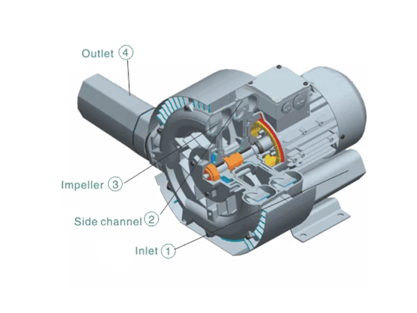
Working principle diagram of regenerative blower with annotations

The impeller of the regenerative blower is directly mounted on the motor rotor, providing completely contactless compression. Since the pump bearings are installed outside the compression chamber, the machine can ensure maximum operational reliability even when working at the highest pressure differentials.

The gas is drawn in through the intake port 1, and as it enters the side channel 2, the rotating impeller 3 imparts velocity to the gas in the direction of rotation, while the centrifugal force on the blades accelerates the gas outward, increasing its pressure. As the rotation continues, the kinetic energy of the gas increases, further raising the pressure of the gas along the side channel. As the side channel narrows at the outlet, the gas is expelled from the pressure chamber and discharged from the pump body through the outlet silencer 4.

Videos
Downloads

Here are product catalogue and data sheet for your reference. more information just contact us.

The nuonuo is answering the phone.
Interested?