
E type mechanical motor dosing pump adopts unique structure design, high efficient and energy saving, and can reduce much more energy consumption than equality motor. Its diaphragm part is made of 100% PTFE material with best quality. Under the long-term experience, the pump could work without liquids and cause no damage to diaphragm. The duckbill valves are being applied in foot valve, no reversed flow, even the pressure become higher and the valve will be sealed better. There are independent switch and fuse in the multi-functional terminal box. It can work with float switch to control the start-stop, being widely used in single pump dosing system.
Technical Specifications
| Model | Capacity L/h |
Pressure Bar |
Stroke Length | Diaphragm Diameter | Pump Speed spm |
Single Capacity | Pipe Size | Power | Electricity | |||
|---|---|---|---|---|---|---|---|---|---|---|---|---|
| 50Hz | 60Hz | 50Hz | 60Hz | mm | mm | 50Hz | 60Hz | ml/stroke | mm | W | ||
| E-9/1.0 | 9 | 10.8 | 10 | 8 | 2 | 70 | 54 | 65 | 2.8 | 6 × 9 | 40 | A: 380V, 3-phase B:220V, single phase |
| E-15/1.0 | 15 | 18 | 10 | 8 | 2 | 70 | 90 | 108 | 2.8 | 6 × 9 | ||
| E-30/0.7 | 30 | 36 | 7 | 5.6 | 4 | 70 | 90 | 108 | 5.6 | 6 × 9 | ||
| E-42/0.7 | 42 | 50.4 | 7 | 5.6 | 3 | 70 | 180 | 216 | 3.9 | 6 × 9 | ||
| E-60/0.5 | 60 | 72 | 5 | 4 | 4 | 70 | 180 | 216 | 5.6 | 6 × 9 | ||
| E-72/0.5 | 72 | 86.4 | 5 | 4 | 5 | 70 | 180 | 216 | 6.67 | 6 × 9 | ||
| E-90/0.3 | 90 | 108 | 3 | 2.4 | 3 | 88 | 180 | 216 | 8.34 | 10 × 14 | ||
| E-120/0.3 | 120 | 144 | 3 | 2.4 | 4 | 88 | 180 | 216 | 11.11 | 10 × 14 | ||
| E-150/0.3 | 150 | 180 | 3 | 2.4 | 5 | 88 | 174 | 209 | 14.37 | 10 × 14 | ||
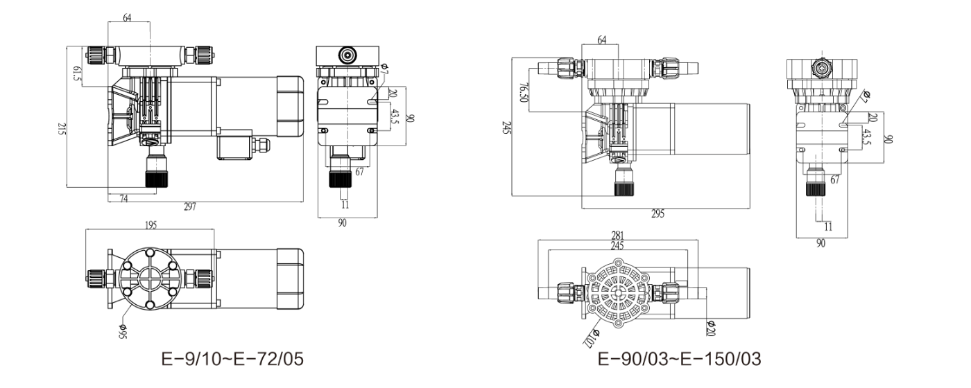
Installation Dimensional Drawing

The motor drives the helical gear reduction box connected with the main shaft to form a reduction mechanical structure. The bearing performs eccentric motion on the eccentric circle of the eccentric shaft, the generated eccentric distance is converted into linear motion of the push rod, and the push rod drives the diaphragm to do line reciprocating motion with the cooperation of the restoring force of the spring.
When the push rod pulls the diaphragm to move backward, the volume between the diaphragm and the pump head increases to generate negative pressure, the one-way valve of the suction pipeline opens, and the medium in the inlet pipeline enters the cavity of the pump head. When the suction stroke ends, the diaphragm movement stops instantly, the pressure in the pump head is balanced with the pressure in the inlet pipe, and the one-way valve of the suction port is reset. During the discharge stroke, the diaphragm connected with the slide bar moves forward, and the pressure in the pump head immediately rises. When the pump head pressure is higher than the outlet pressure, the outlet check valve is opened, and the medium in the pump head enters the discharge line. When the discharge stroke ends, the diaphragm movement stops again, the pressure in the pump head is equal to the outlet pressure, and the outlet check valve resets, and then enters the next cycle.

Here are product catalogue and data sheet for your reference. more information just contact us.