

One-Stop Water Treatment Solutions Provider
- Home
- Why Snowate
- Parts
-
Desalination High Pressure Pump
-
CNP Pump
-
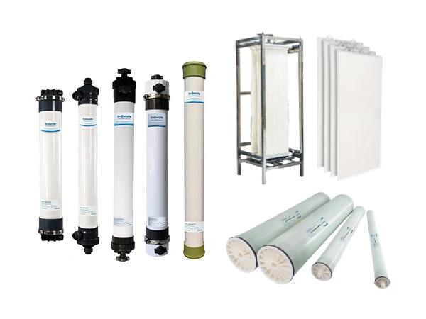
EDI Module
-
Membranes
-
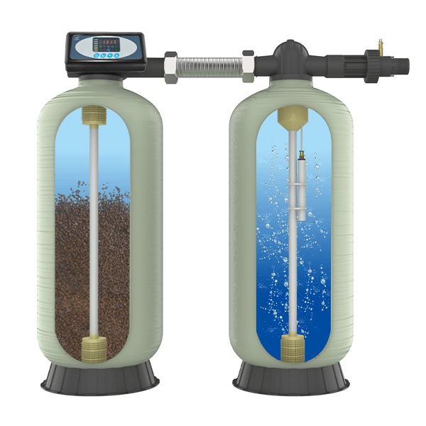
Ion Exchange Resins
-
Water Treatment Chemicals
-
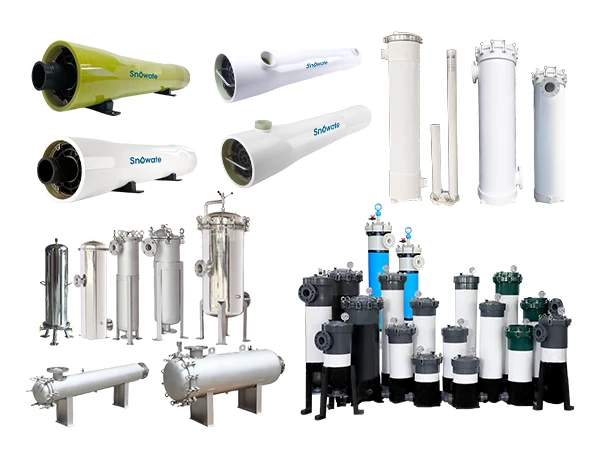
Precision/Security Filter Housing
-
Self-Cleaning Filter Housing
-
Food & Pharmaceutical Filter Housing
-
Filter Cartridges
-
Filter Bags
-
Thermoplastic Valves
-
Metal Valve
-
Supmea Instrument
-
CREATEC Instrument
-
Pressure gauge
-
Solenoid Valve
-
Flow Meter
-
SEKO Dosing Pump
-
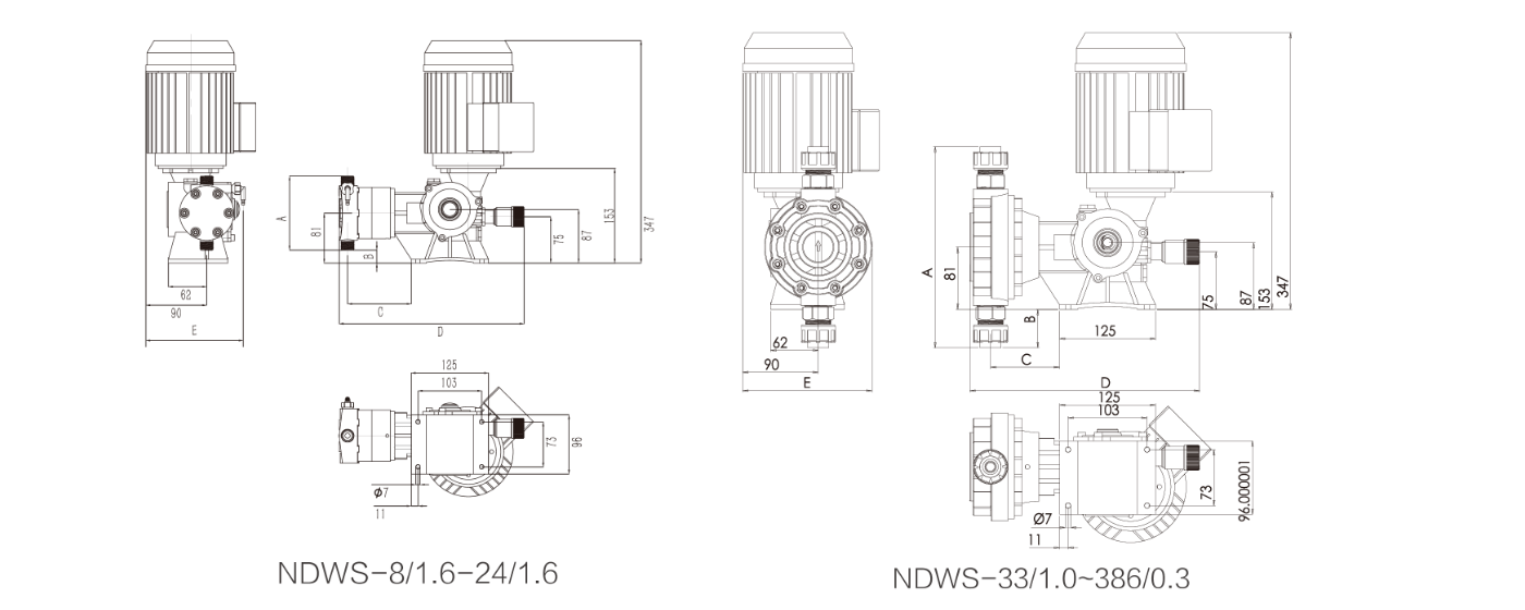
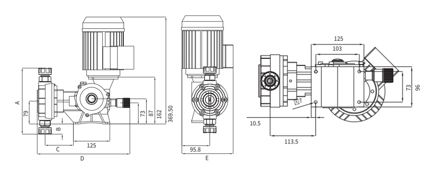
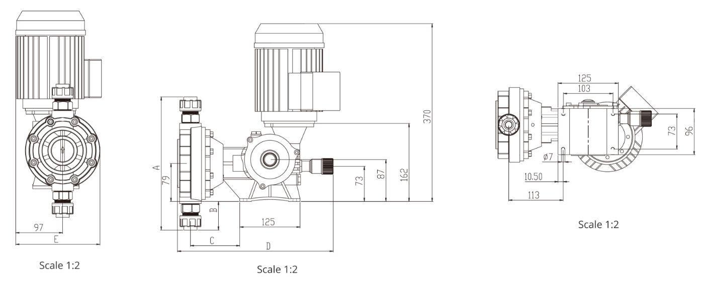
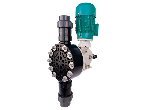
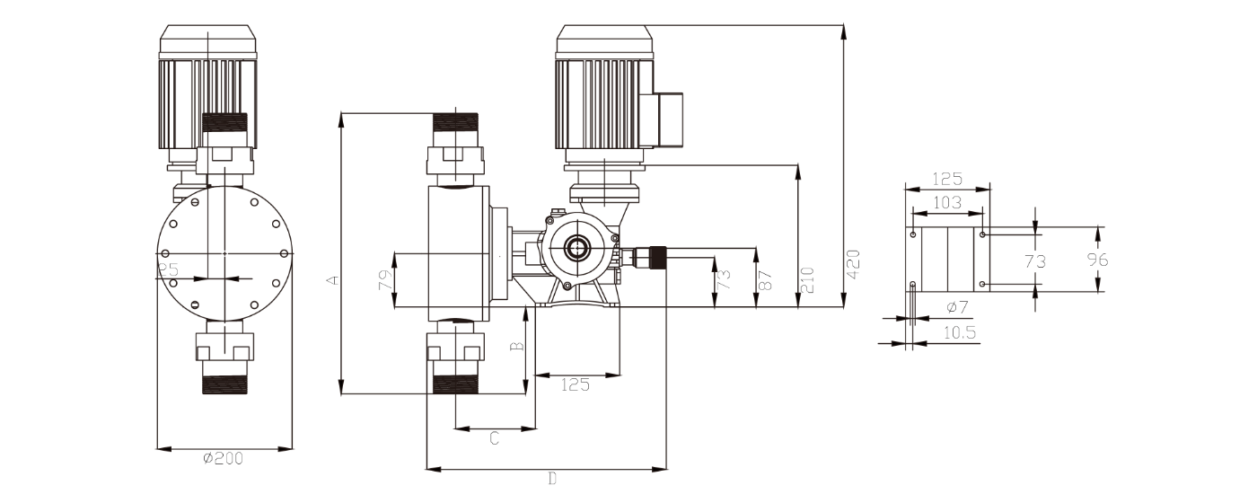
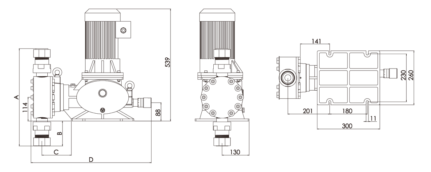
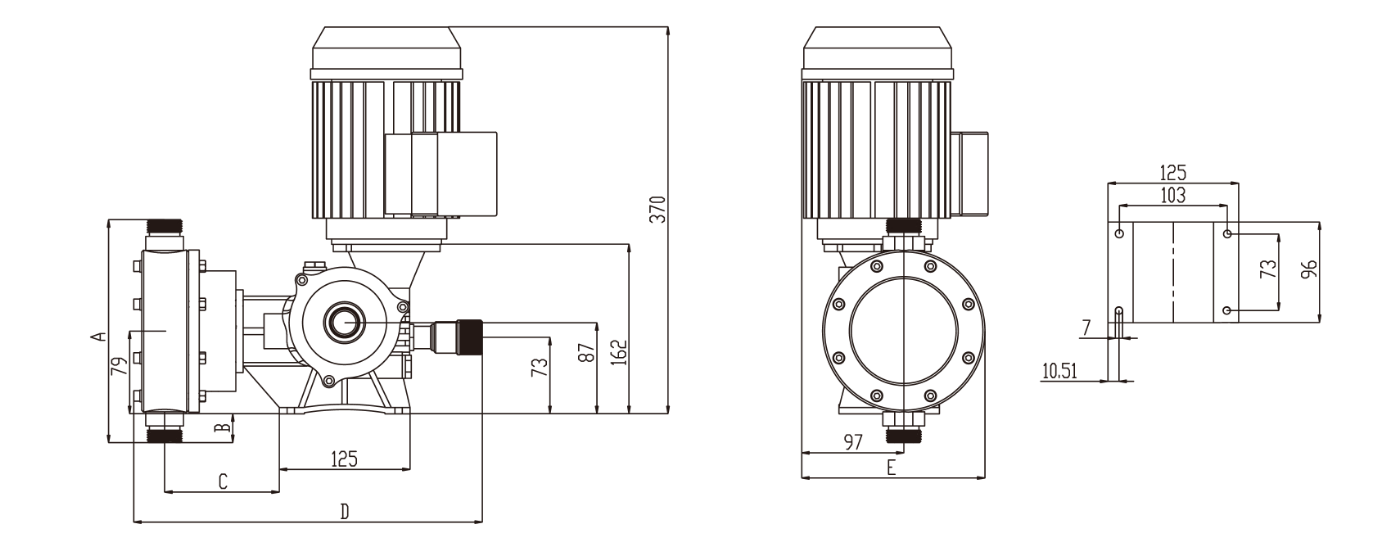
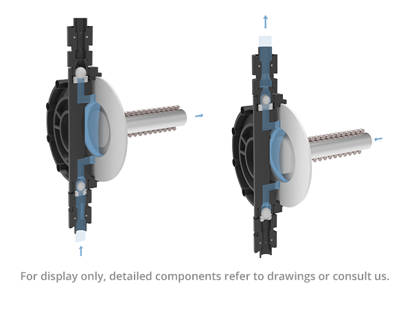
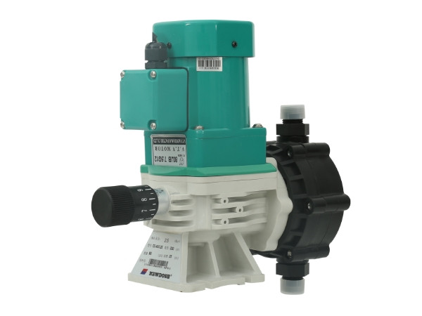
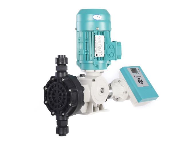
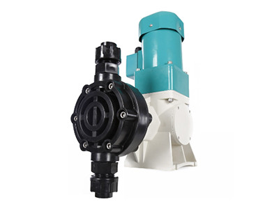
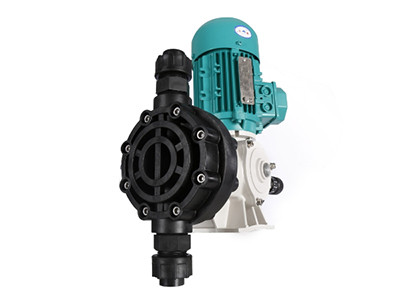
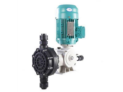
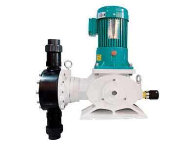
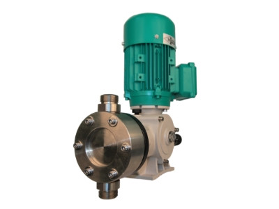
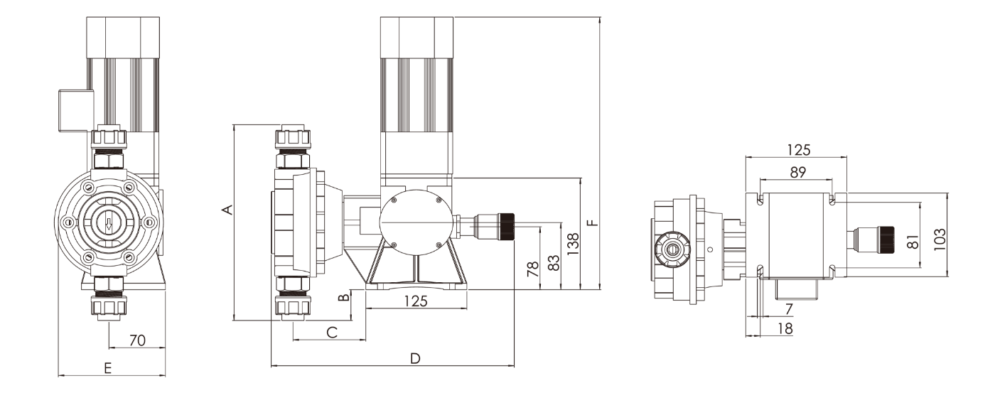
Snowate Metering Pump
-
Plastic Valves & Fittings
-
UV Water Sterilizer
-
Ozone Generator
-
Industrial Ozone Generator
-
Chlorinated Disinfection Equipment
-
Multiport Control Valves
-
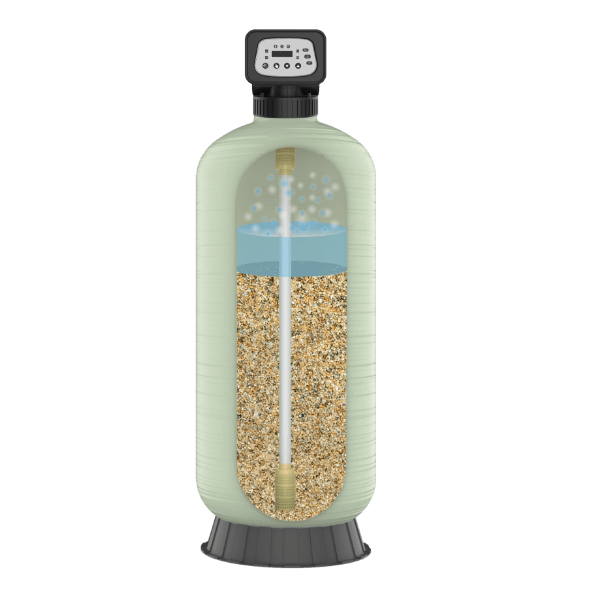
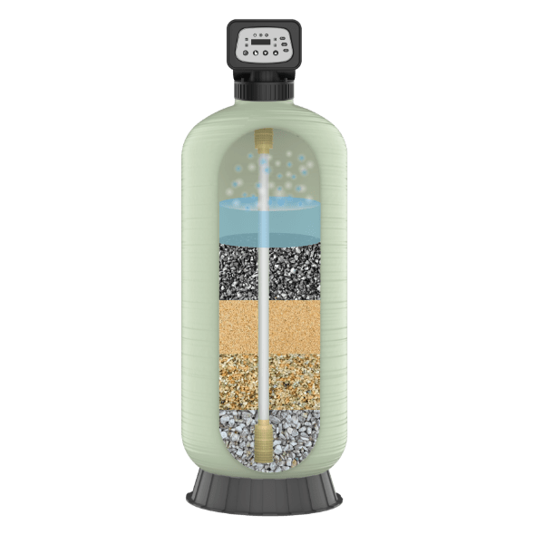
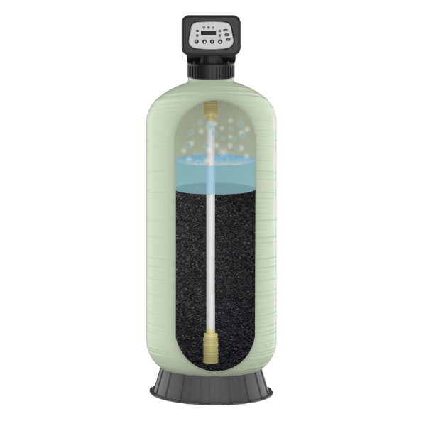
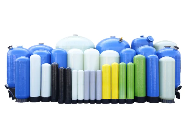
FRP Tanks
-
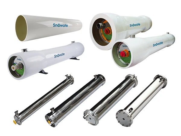
Membrane Housings
-
Butt Weld Fittings
-
Pipe Fittings
-
Pump Pressure Controller
-
Automation Control
-
Wastewater Treatment
-
- Systems
- Industry
- Solutions
- Knowledge & Calculator
- Resources
- Contact