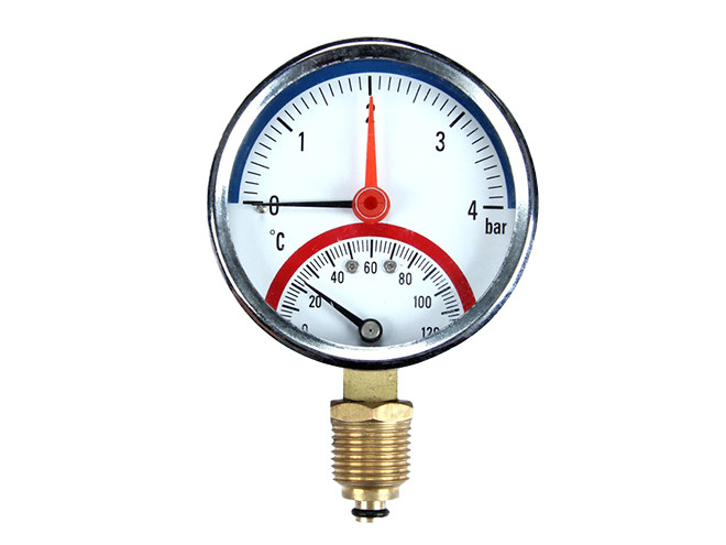
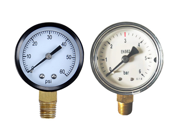
2 special pressure gauge are displayed.

Special Pressure Gauges Specially Designed For Complex Environments

Special pressure gauges are compared to ordinary pressure gauges. In terms of pressure range, special pressure gauge can be optimized and calibrated for specific pressure ranges to adapt to special environments or precise measurement needs. In terms of panel design, special pressure gauge adds a temperature indication to meet the needs of specific industrial or research fields. In terms of uses, ordinary pressure gauges are usually used in general industrial water treatment, while special pressure gauges are designed for specific application environments and requirements, such as the food industry, biopharmaceuticals, and other high-demand industries.

  • Specifications
  • Structure
  • Working Principle
  • Video
Specification
  • Nominal diameter: φ40, φ50, φ60, φ100
  • Accuracy level: 1.6
  • Pressure range: -0.1 MPa, 0.16 MPa, 0.4 MPa, 0.6 MPa, 0.7 MPa, 1 MPa, 1.6 MPa, 2.5 MPa, 3 MPa, 4 MPa, 6 MPa, 10 MPa
  • Installation method: Radial installation, axial installation, axial edge installation
  • Interface size: ZG1/2", M20×1.5
  • Wetted material: Copper plated nickel (commonly used), stainless steel, brass
  • Case material: Plastic, SS304, SS316
  • Movement material: Main body copper
  • Pressure sensing element: C-type Bourdon Tube
  • Instrument pointer: aluminum
Structure
Pressure gauge structure diagram with annotations
  • Dial. A circular disk with different pressure unit scales, often works with the pointer to visually read data.
  • Pointer. Fixed above the dial, connected to the sector gear chain, used to indicate the pressure reading on the dial.
  • Bourdon tube. C-shaped or spiral metal tube used to convert the measured pressure into deformation inside the Bourdon tube, forming the basis for measuring pressure changes.
  • End piece. The free end of the Bourdon tube, connected to the transmission mechanism. When the internal pressure of the Bourdon tube changes, the free end produces the maximum displacement.
  • Link. It connects the free end of the Bourdon tube to the pointer mechanism, converting the small deformation of the Bourdon tube into rotational motion of the pointer.
  • Sector gear and rack. The rack is connected to the free end of the Bourdon tube and meshes with the sector gear, amplifying linear motion and converting it into rotational motion of the pointer
  • Stem with pressure connector. It connects the pressure gauge to the pressure source, supports the connection joint, and allows pressure to be transmitted from the connection point to the Bourdon tube.
Working Principle
Pressure gauge working principle diagram with annotations

When the pressure of the tested system is transmitted to the Bourdon tube through the interface of the pressure gauge, the pressure inside the Bourdon tube will push the tube wall to deform. One end of the Bourdon tube is usually closed and connected to the pointer mechanism. As the Bourdon tube deforms, the closed end will produce displacement. The displacement is converted into the rotational motion of the pointer through a mechanical linkage system (including a sector gear and a rack), and the pointer points to a specific value on the dial, which represents the pressure inside the Bourdon tube.

Videos
Downloads

Here are product catalogue and data sheet for your reference. more information just contact us.

The nuonuo is answering the phone.
Interested?