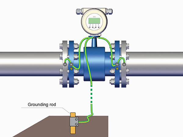
Setting up grounding devices for electromagnetic flowmeter sensors can ensure the normal operation and accurate measurement of the flowmeter, while also providing functions such as electrical safety, interference suppression, static elimination, and equipment protection. The specific implementation of sensor grounding varies depending on the model of the electromagnetic flowmeter and the installation conditions of the sensor. A correct grounding device can ensure reliable and stable transmitter operation, enabling precise fluid measurement.

Selection of Installation Location
In order to ensure reliable and stable transmitter operation, the following requirements should be considered when selecting the installation location:

Grounding devices for different installation conditions
Since general metal pipelines are connected to the ground, the flowing medium is connected to the ground through the metal pipeline. Therefore, it is generally not necessary to separately install grounding devices, especially for small-diameter electromagnetic flowmeter sensors. However, separately installing grounding devices is beneficial for the reliable operation of the instrument.
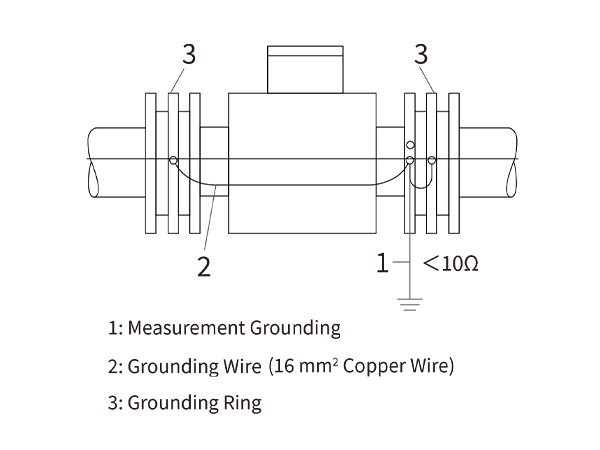
When the sensor is installed on an insulated pipeline, metal short pipes and grounding rings must be installed at both ends to establish a connection with the fluid. If the measured fluid is highly corrosive and it is difficult to install metal short pipes and grounding rings, grounding electrodes can be installed by drilling holes on the insulated pipeline at both ends of the sensor. The grounding electrodes are made of corrosion-resistant alloy materials and are connected to the sensor's grounding screw with a wire.

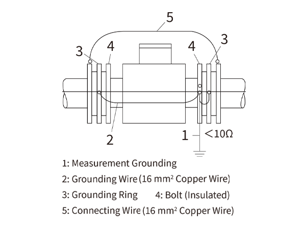
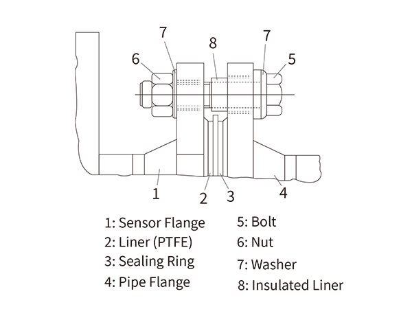
For sensors installed on pipelines with cathodic corrosion protection, they should be insulated from the pipeline. The installation of the sensor must pay attention to the following points.


In places where there is strong stray current in the pipeline, such as measuring the flow of electrolyte in the pipeline near the electrolytic cell, the stray current will cause serious interference. In this case, the installation and grounding method shown in the figure below can be used. Insulated pipelines are connected to both ends of the sensor, and a grounding ring is installed between the sensor and the insulated pipeline. Similar to the general installation and grounding method, the grounding ring is connected to the grounding rod with good grounding together with the flange of the sensor. The process pipelines on both sides of the insulated pipeline are short-circuited with connecting wires. In this way, the leakage current is mainly diverted and short-circuited through the connecting copper wire, greatly reducing the interference introduced into the sensor signal circuit from the measured liquid. When the installation environment has strong leakage current and electric field effects, the sensor must be grounded separately. The ground wire should be a multi-stranded copper wire with a total cross-sectional area of not less than 16 mm2, connected to a grounding rod buried at a certain depth.

The above is the grounding device settings for electromagnetic flowmeter sensors installed in different environments. You can refer to them when installing and setting up the grounding device. If you encounter a special installation environment where you cannot determine the grounding device, you can contact us, and we will do our best to assist you.