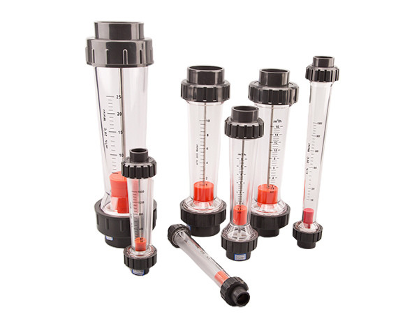
Four pieces of variable area flow meter with alarm limit switch.

Variable-Area Flow Meter with Alarm Switch for Immediate Abnormality Feedback

The variable-area flow meter with alarm switches is a setup where BJ01 upper limit alarm and BJ02 lower limit alarm switches are added to the existing flow meter's measurement tube on the dovetail guide rails. The alarm switches can signal at any flow value, whether it be maximum, intermediate, or minimum. When the magnetic float reaches or exceeds the switch position, it utilizes the bistable magnetic action of a reed switch, which enables the flow meter and the magnetic float to open and close contacts. This mechanism is used in conjunction with relay components and other elements to meet the requirements for audible and visual alarms.

  • Specifications
  • Working Principle
  • Structure
  • Video
Specification
Table 1: SVF LZM Series Panel-Type Variable-Area Flow Meter With Alarm Switch Specifications
Model Measurement Range Interface Thread Accuracy (±%)
Liquid (GPM) Liquid (LPM) Gas (Nm3/h)
SF LZM-15, SF LZM-15J 0.2–2 0.8–8 ZG1/2"M ±4
0.3–3 1–11 ZG1/2"M ±4
0.5–5 2–18 ZG1/2"M ±4
1–7 2–28 ZG1/2"M ±4
SF LZM-20, SF LZM-20J 2–10 8–40 6–60, 16–80, 16–160 ZG3/4"M ±4
2–16 8–60 6–60, 16–80, 16–160 ZG3/4"M ±4
2–20 8–80 6–60, 16–80, 16–160 ZG3/4"M ±4
SF LZM-25, SF LZM-25J 1.5–15 6–60 ZG1"M ±4
3–13 10–50 ZG1"M ±4
4–24 10–100 ZG1"M ±4
5–35 10–130 ZG1"M ±4
5–45 10–170 ZG1"M ±4
SF LZM-15Z 0.1–1 0.5–4 0.3–3, 0.4–4, 0.6–6, 1–10, 2.5–25, 4–40 ZG1/2"M, ZG1/4"F ±4
0.15–1.5 0.6–6 0.3–3, 0.4–4, 0.6–6, 1–10, 2.5–25, 4–40 ZG1/2"M, ZG1/4"F ±4
0.2–2 1–7 0.3–3, 0.4–4, 0.6–6, 1–10, 2.5–25, 4–40 ZG1/2"M, ZG1/4"F ±4
0.3–3 1–11 0.3–3, 0.4–4, 0.6–6, 1–10, 2.5–25, 4–40 ZG1/2"M, ZG1/4"F ±4
0.5–5 2–18 0.3–3, 0.4–4, 0.6–6, 1–10, 2.5–25, 4–40 ZG1/2"M, ZG1/4"F ±4
SF LZM-25Z 1–10 5–35 ZG1"M ±4
1–15 5–50 ZG1"M ±4
2–14 10–50 ZG1"M ±4
2–20 10–70 ZG1"M ±4
5–35 10–130 ZG1"M ±4
5–40 10–150 ZG1"M ±4
5–45 10–170 ZG1"M ±4
0.3–2.1 m3/h ZG1"M ±4
0.6–3 m3/h ZG1"M ±4
0.6–4.2 m3/h ZG1"M ±4
SF LZM-15G 0.1–1 0.5–4 1–10, 1.6–16, 2.5–25, 4–40 G1/2"F ±4
0.2–2 1–7 1–10, 1.6–16, 2.5–25, 4–40 G1/2"F ±4
0.5–5 1.8–18 1–10, 1.6–16, 2.5–25, 4–40 G1/2"F ±4
1.5–9 400–2000 LPH 1–10, 1.6–16, 2.5–25, 4–40 G1/2"F ±4
SF LZM-20G 1–10 6–60 G3/4"F ±4
SF LZM-25G, SF LZM-40G 1–15 5–60 25G, G1"F
40G, G1-1/2"M
±4
2–20 10–70 25G, G1"F
40G, G1-1/2"M
±4
5–30 20–110 25G, G1"F
40G, G1-1/2"M
±4
5–40 20–150 25G, G1"F
40G, G1-1/2"M
±4
SF LZM-50G 20–80 80–300 100–500 G2"F, G2"M ±4
20–100 80–360 120–600 G2"F, G2"M ±4
40–120 150–450 300–850 G2"F, G2"M ±4
50–150 190–560 400–1200 G2"F, G2"M ±4
60–200 220–750 500–1400 G2"F, G2"M ±4
Table 2: lSVF LZS Series Plastic Pipe Type with Alarm Switch Specification
Model Nominal Diameter (mm) Measurement Range Accuracy (±%) Allowed Measured Medium Condition
Long Tube Type Short Tube Type Temperature (°C) Pressure (MPa)
SVF LZS-15 15 10–100 L/h, 16–160 L/h, 25–250 L/h, 40–400 L/h, 60–600 L/h 5–50 L/h, 10–100 L/h, 16–160 L/h, 25–250 L/h, 40–400 L/h, 50–500 L/h, 60–600 L/h, 100–1000 L/h ±4 0–60°C ≤0.6
SVF LZS-25 25 100–1000 L/h, 160–1600 L/h, 250–2500 L/h 100–1000 L/h, 160–1600 L/h, 4–40 L/min, 250–2500 L/h
SVF LZS-32 32 0.4–4 m3/h, 0.6–6 m3/h
SVF LZS-50 50 0.4–4 m3/h, 0.6–6 m3/h, 1–10 m3/h, 1.6–16 m3/h 1–10 m3/h, 1.6–16 m3/h
SVF LZS-60 60 2.5–16 m3/h, 5–25 m3/h, 8–40 m3/h, 12–60 m3/h
SVF LZS-100 100 14–90 m3/h, 18–120 m3/h, 20–150 m3/h, 25–180 m3/h, 25–200 m3/h 14–90 m3/h, 18–120 m3/h, 20–150 m3/h, 25–18 0m3/h, 25–200 m3/h
SVF LZS-125 125
SVF LZS-150 150
Note: SVF LZS-100, 125, 150 specifications flowmeter can be customized with alarm switch
Table 3: SR LZB Small Glass Rotor with Alarm Switch Specification
Model LZB-6 LZB-10 LZB-15 LZB-25
Nominal Diameter (mm) φ6 φ10 φ15 φ25
Measurement Range Liquid (L/h) 1–10 6–60 *6–60 40–400
2.5–25 10–100 *8–80 60–600
4–40 16–160 16–160 100–1000
6–60 25–250 25–250 *160–1600
40–400
Gas (Nm3/h) 0.06–0.6 0.1–1 0.25–2.5 *0.8–8
0.16–1.6 0.4–4 1–10
0.25–2.5 0.6–6 1.6–16
0.4–4 2.5–25
0.6–6
Accuracy (±%) 2.5 2.5 2.5 1.5
Operating Pressure (MPa) ≤1 ≤1 ≤1 ≤0.6
Note: Flow rates marked with "*" are special flow rates
Table 4: lSR LZB Large Glass Rotor with Alarm Switch Specification
Model SR LZB-40 SR LZB-50 SR LZB-80 SR LZB-100 SR LZB-100
Nominal Diameter (mm) ɸ40 ɸ50 ɸ80 ɸ100 ɸ100
Measurement Range Liquid (L/h) 160–1600 *160–1600 1–10 m3/h 5–25 m3/h *20–90 m3/h
*180–1800 400–4000 1.6–16 m3/h *6–35 m3/h *20–100 m3/h
250–2500 600–6000 *2–20 m3/h 8–40 m3/h *30–100 m3/h
*300–3000 *800–8000 *3–25 m3/h *12–60 m3/h *50–120 m3/h
*400–4000 *1–10 m3/h *8–40 m3/h *16–80 m3/h
Gas (Nm3/h) *1–5 m3/h *4–16 m3/h
*1.5–6 m3/h
4–40 *6–60 50–250 *60–200 *300–1500
*5–50 10–100 80–400 *80–400 *300–1600
6–60 16–160 *750–7500 L/min *100–500 *400–2000
*7–70 *20–200 *6–60 120–600 *500–2500
*8–80 *30–300 200–1000
*10–100 *50–250
*80–400
Accuracy (±%) 1.5 1.5 1.5 1.5 1.5
Operating Pressure (MPa) ≤0.6 ≤0.6 ≤0.4 ≤0.4 ≤0.4
Note: Flow rates marked with "*" are special flow rates
Table 5: SR LZB-VA/WA/FA30S Type Rotameter with Alarm Switch
Model Nominal Diameter DN (mm) Measurement Range Accuracy (±%) Operating Temperature (°C) Operating Pressure (MPa)
20 °C water (L/h) 20 °C Air: 101325 Pa (m3/h)
SR LZB-VA30S-15, SR LZB-FA30S-15, SR LZB-WA30S-15 15 4–40, 6.3–63, 10–100, 12–120, 16–160, 20–200, 25–250, 30–300, 36–360, 40–400, 46–460, 63–630, 65–650, 75–750 0.12–1.2, 0.2–2, 0.3–3, 0.4–4, 0.5–5, 0.6–6, 0.8–8, 0.9–9, 1.2–12, 2–20 ±1.5 -20 °C to +80°C ≤1
SR LZB-VA30S-25, SR LZB-FA30S-25, SR LZB-WA30S-25 25 40–400, 50–500, 63–630, 80–800, 100–1000, 120–1200, 160–1600, 200–2000, 250–2500, 300–3000 1.6–16, 2–20, 2.5–25, 3–30, 4–40, 5–50, 6–60
SR LZB-VA30S-40, SR LZB-FA30S-40, SR LZB-WA30S-40 40 160–1600, 200–2000, 250–2500, 300–3000, 400–4000, 600–6000 5–50, 6–60, 8–80, 9–90, 12–120 ≤0.9
SR LZB-VA30S-50, SR LZB-FA30S-50, SR LZB-WA30S-50 50 250–2500, 300–3000, 400–4000, 500–5000, 630–6300, 800–8000, 1000–10000, 1500–15000, 4000–16000 10–100, 12–120, 16–160, 20–200, 30–300 ≤0.7

Technical parameters

  • Maximum Operating Voltage: DC 100V / AC 100V
  • Maximum Operating Current: 0.3A
  • Maximum Switching Current: 0.5A
  • Maximum Interrupting Power: 0.5VA
  • Operating Temperature Range: 0°C to 55°C
  • Insulation Impedance: >10^9 Ω
  • Protection Level: IP65
  • Hysteresis (Open or Close Position): ≤4 mm
  • Dimensions: 42x20x38 mm

Applications and Functions

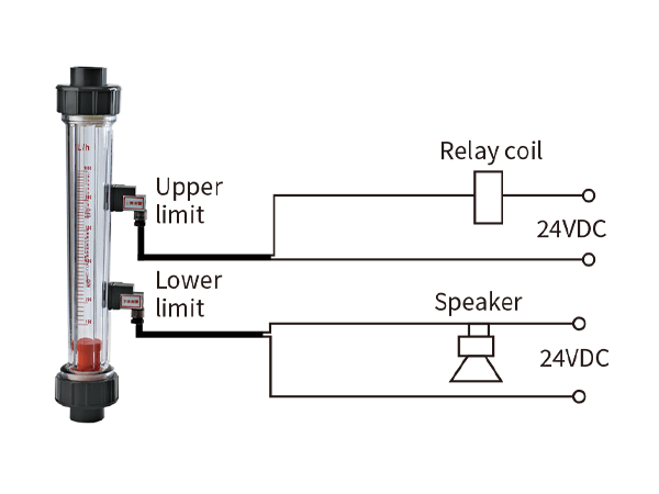
  • Upper Limit Alarm: When the magnetic float is exactly at the switch set position, the contact is closed. When the magnetic float is above the switch set position, the contact remains closed. When the magnetic float is below the switch set position, the contact opens.
  • Lower Limit Alarm: When the magnetic float is exactly at the switch set position, the contact is closed. When the magnetic float is below the switch set position, the contact remains closed. When the magnetic float is above the switch set position, the contact opens.
Wiring diagram of relay coils for upper limit alarm and lower limit alarm of the flow meter
Wiring diagram of PLC coils for upper limit alarm and lower limit alarm of the flow meter
Working Principle
Structure
Videos
Downloads

Here are product catalogue and data sheet for your reference. more information just contact us.

The nuonuo is answering the phone.
Interested?