SF LZT-4T

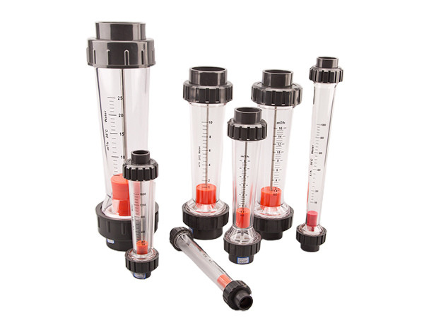
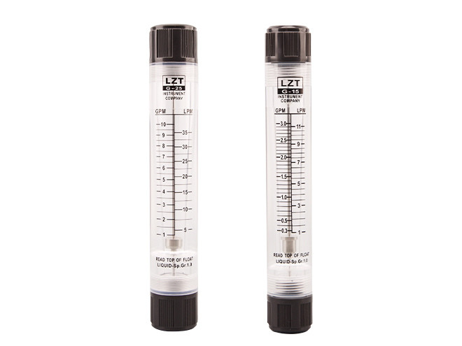
SF LZT series acrylic glass flow meter is a acrylic-based flow meter for measuring single-phase non-pulsating flow of liquids or gases. It has the characteristics of high transparency, beautiful appearance, light weight, unbreakable and long service life. It is usually used for the measurement of clear or low viscosity fluids, such as water and solution.
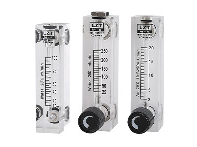
SF LZT-4T, 6T, 8T Series
SF LZT Series
SF LZT-L Series
SF LZT-T/L-T
SF LZT-G/GL Series
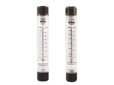
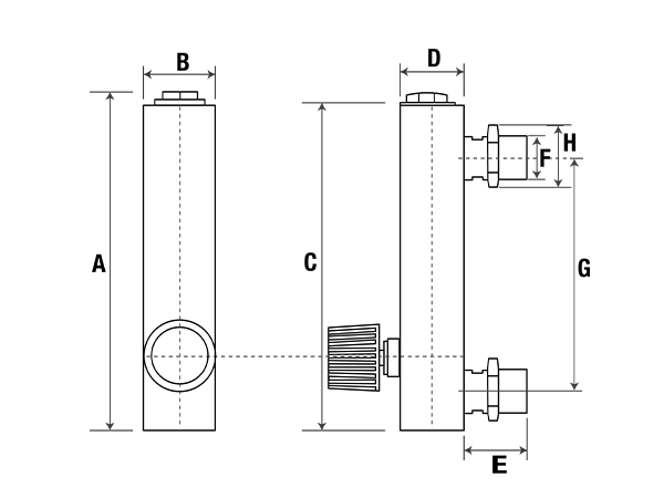
SF LZT-4T, 6T, 8T series panel type flow meter is installed with a regulating valve. Brass material regulating valve has good thermal conductivity and corrosion resistance, is suitable for some special fluids and industrial environments, and plays an important role in fluid flow control, which can achieve precise flow adjustment, flow stabilization, energy saving, equipment protection, and other functions.
Parts and components of conventional material:
Technical Parameter
| Model | Range | Interface | Accuracy (±%) | |
|---|---|---|---|---|
| Liquid (ml/min) | Air (l/min) | |||
| SF LZT-4T | 6–60, 8–80, 10–100, 40–400 | 0.1–1, 0.2–2, 0.25–2.5, 0.6–6, 1–4, 1–10, 1–12 | Plug-in | ±4 |
| SF LZT-6T | 2–20 LPH, 4–40 LPH, 6–60 LPH, 10–100 LPH, 10–70 GPH | 0.1–1, 0.2–2, 0.25–2.5, 0.5–5, 0.6–6, 1–10, 1–12, 2–20, 3–30, 4–40, 5–50, 6–60, 10–100, 15–150 | Thread: ZG1/4" F | ±4 |
| SF LZT-8T | 2.5–25 LPH, 5–45 LPH, 6–60 LPH | 0.1–1 m3/h, 0.16–1.6 m3/h, 0.2–2 m3/h | Thread: ZG1/4" F | ±4 |
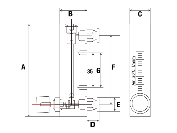
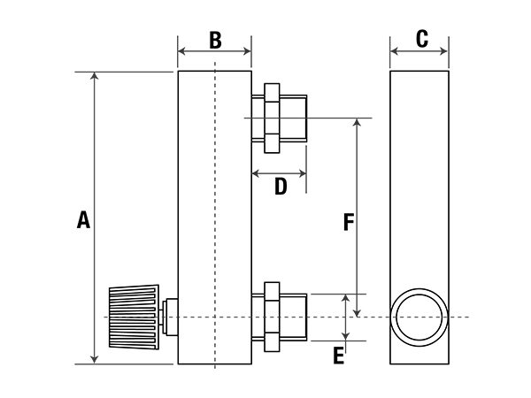
Drawings & dimension
SF LZT-4T
SF LZT-6T, 8T
| Model | Size (mm) | |||||
|---|---|---|---|---|---|---|
| A | B | C | D | E | F | |
| SF LZT-4T | 94 | 28 | 21.6 | 14 | 14 | 70 |
| SF LZT-6T | 102 | 30.6 | 25.6 | 18 | M18 × 1.5 | 76 |
| SF LZT-8T | 110 | 25 | 25 | 18 | M18 × 1.5 | 80 |
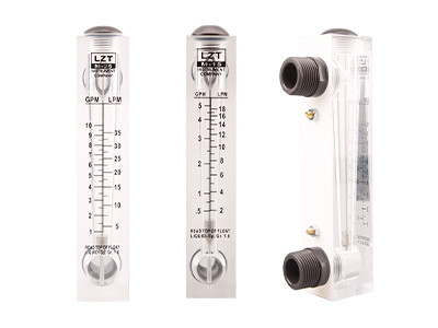
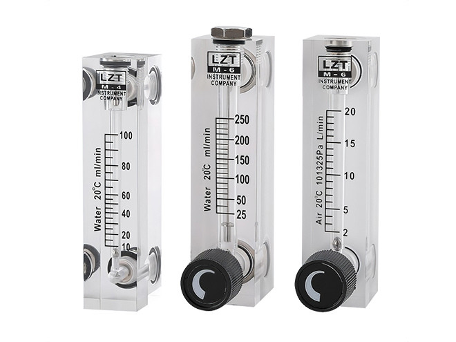
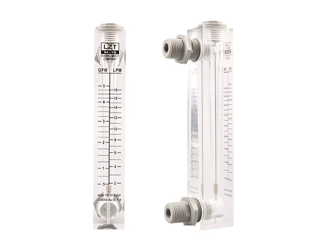
SF LZT-series panel type flow meters are typically used to measure the flow of a fluid without regulating the flow, and they provide accurate flow measurement results. This series of flow meter is suitable for applications that do not require flow adjustment, such as flow monitoring, flow control and fluid analysis.
Parts and components of conventional material:
Technical Parameter
| Model | Range | Interface | Accuracy (±%) | ||
|---|---|---|---|---|---|
| Liquid (GPM) | Liquid (LPM) | Air (Nm3/h) | |||
| SF LZT-15 | – | 6–60 LPH, 10–100 LPH, 16–160 LPH, 25–250 LPH, 40–400 LPH | 0.1–1, 0.16–1.6, 0.25–2.5, 0.3–3, 0.4–4, 0.6–6, 1–10, 1.6–16, 2–20, 2.5–25, 3–30, 4–40, 12–120 LPM, 24–240 LPM, 48–480 LPM, 72–720 LPM | ZG1/2" M, ZG1/4" F | ±4 |
| 0.05–0.5 | 0.2–2 | 0.1–1, 0.16–1.6, 0.25–2.5, 0.3–3, 0.4–4, 0.6–6, 1–10, 1.6–16, 2–20, 2.5–25, 3–30, 4–40, 12–120 LPM, 24–240 LPM, 48–480 LPM, 72–720 LPM | ZG1/2" M, ZG1/4" F | ±4 | |
| 0.1–1 | 0.5–4 | 0.1–1, 0.16–1.6, 0.25–2.5, 0.3–3, 0.4–4, 0.6–6, 1–10, 1.6–16, 2–20, 2.5–25, 3–30, 4–40, 12–120 LPM, 24–240 LPM, 48–480 LPM, 72–720 LPM | ZG1/2" M, ZG1/4" F | ±4 | |
| 0.2–2 | 1–7 | 0.1–1, 0.16–1.6, 0.25–2.5, 0.3–3, 0.4–4, 0.6–6, 1–10, 1.6–16, 2–20, 2.5–25, 3–30, 4–40, 12–120 LPM, 24–240 LPM, 48–480 LPM, 72–720 LPM | ZG1/2" M, ZG1/4" F | ±4 | |
| 0.3–3 | 1–11 | 0.1–1, 0.16–1.6, 0.25–2.5, 0.3–3, 0.4–4, 0.6–6, 1–10, 1.6–16, 2–20, 2.5–25, 3–30, 4–40, 12–120 LPM, 24–240 LPM, 48–480 LPM, 72–720 LPM | ZG1/2" M, ZG1/4" F | ±4 | |
| 0.5–5 | 2–18 | 0.1–1, 0.16–1.6, 0.25–2.5, 0.3–3, 0.4–4, 0.6–6, 1–10, 1.6–16, 2–20, 2.5–25, 3–30, 4–40, 12–120 LPM, 24–240 LPM, 48–480 LPM, 72–720 LPM | ZG1/2" M, ZG1/4" F | ±4 | |
| SF LZT-20 | 1–10 | 5–35 | 2.5–25, 3–30, 4–40, 6–60, 10–100 | ZG3/4" M | ±4 |
| 2–16 | 4–60 | 2.5–25, 3–30, 4–40, 6–60, 10–100 | ZG3/4" M | ±4 | |
| 2–14 | 12–52 | 2.5–25, 3–30, 4–40, 6–60, 10–100 | ZG3/4" M | ±4 | |
| SF LZT-25 | 1–10 | 5–35 | 2.5–25, 3–30, 4–40, 6–60, 10–100, 16–160, 25–250, 30–300 | ZG1" M | ±4 |
| 2–16 | 4–60 | 2.5–25, 3–30, 4–40, 6–60, 10–100, 16–160, 25–250, 30–300 | ZG1" M | ±4 | |
| 2–14 | 12–52 | 2.5–25, 3–30, 4–40, 6–60, 10–100, 16–160, 25–250, 30–300 | ZG1" M | ±4 | |
| 2–20 | 10–70 | 2.5–25, 3–30, 4–40, 6–60, 10–100, 16–160, 25–250, 30–300 | ZG1" M | ±4 | |
| 5–35 | 20–130 | 2.5–25, 3–30, 4–40, 6–60, 10–100, 16–160, 25–250, 30–300 | ZG1" M | ±4 | |
| 4–40 | 15–150 | 2.5–25, 3–30, 4–40, 6–60, 10–100, 16–160, 25–250, 30–300 | ZG1" M | ±4 | |
| 5–45 | 20–170 | 2.5–25, 3–30, 4–40, 6–60, 10–100, 16–160, 25–250, 30–300 | ZG1" M | ±4 | |
| SF LZT-40 | 4–40 | 15–150 | – | ZG1-1/2" M, NPT1-1/2" M | ±4 |
| 10–60 | 25–250 | – | ZG1-1/2" M, NPT1-1/2" M | ±4 | |
| 10–80 | 30–300 | – | ZG1-1/2" M, NPT1-1/2" M | ±4 | |
| 10–80 | 50–300 | – | ZG1-1/2" M, NPT1-1/2" M | ±4 | |
| 10–100 | 50–350 | – | ZG1-1/2" M, NPT1-1/2" M | ±4 | |
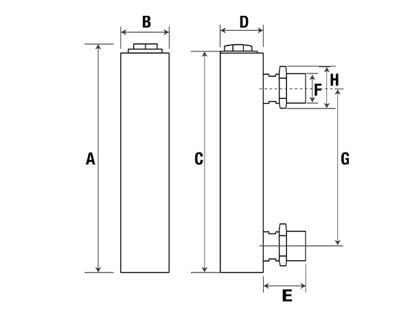
Drawings & dimension

| Model | Size (mm) | |||||||
|---|---|---|---|---|---|---|---|---|
| A | B | C | D | E | F | G | H | |
| SF LZT-15 | 175 | 32 | 168 | 35 | 25 | 76 | 25 | 127 |
| SF LZT-20 | 236 | 45 | 228 | 46 | 33 | 101.6 | 37 | 165 |
| SF LZT-25 | ||||||||
| SF LZT-40 | 267 | 65 | 250 | 68 | 33 | 100 | 58 | 170 |
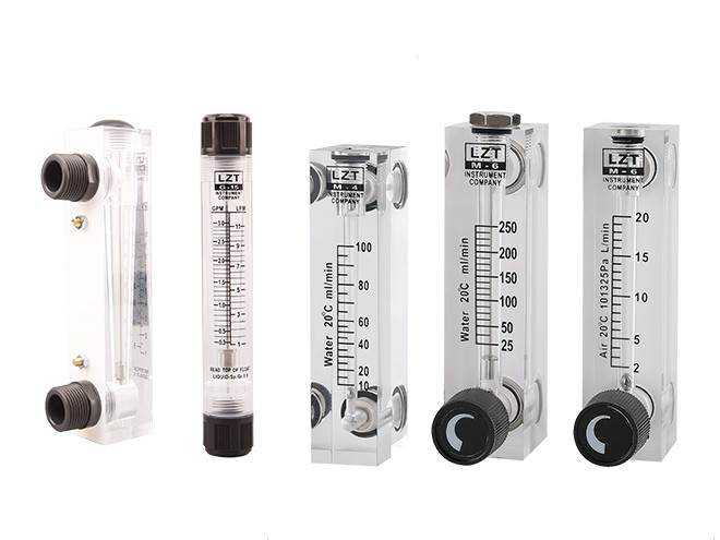
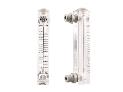
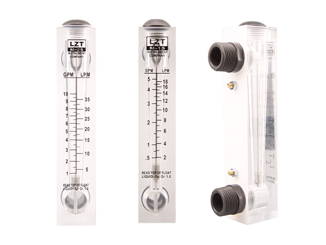
SF LZT-L series panel type flow meter in the length of the panel to do the size of the extended processing, so that the panel can have better visibility, can provide a larger digital display area, to ensure more accurate readings. At the same time, the flow meter series uses an external thread connection, so that the interface is relatively simple to install and remove.
Parts and components of conventional material:
Technical Parameter
| Model | Range | Interface | Accuracy (±%) | ||
|---|---|---|---|---|---|
| Liquid (GPM) | Liquid (LPM) | Air (Nm3/h) | |||
| SF LZT-15L | 0.1–1 | 0.5–4 | 1–10, 1.6–16, 4–40 | ZG1/2" M, NPT1/2" M | ±4 |
| 0.2–2 | 1–7 | 1–10, 1.6–16, 4–40 | ZG1/2" M, NPT1/2" M | ±4 | |
| 0.3–3 | 1–11 | 1–10, 1.6–16, 4–40 | ZG1/2" M, NPT1/2" M | ±4 | |
| 0.5–5 | 2–18 | 1–10, 1.6–16, 4–40 | ZG1/2" M, NPT1/2" M | ±4 | |
| 1–7 | 2–28 | 1–10, 1.6–16, 4–40 | ZG1/2" M, NPT1/2" M | ±4 | |
| 1.5–9 | 5–35 | 1–10, 1.6–16, 4–40 | ZG1/2" M, NPT1/2" M | ±4 | |
| SF LZT-20L | 2–10 | 8–40 | 2.5–25, 6–60, 16–160 | ZG3/4" M, NPT3/4" M | ±4 |
| 2–16 | 10–60 | 2.5–25, 6–60, 16–160 | ZG3/4" M, NPT3/4" M | ±4 | |
| 2–20 | 8–80 | 2.5–25, 6–60, 16–160 | ZG3/4" M, NPT3/4" M | ±4 | |
| SF LZT-25L | 1.5–15 | 6–60 | 20–200, 25–250 | ZG1" M, NPT1" M | ±4 |
| 3–13 | 5–50 | 20–200, 25–250 | ZG1" M, NPT1" M | ±4 | |
| 4–24 | 10–100 | 20–200, 25–250 | ZG1" M, NPT1" M | ±4 | |
| 5–35 | 20–130 | 20–200, 25–250 | ZG1" M, NPT1" M | ±4 | |
| 5–45 | 20–170 | 20–200, 25–250 | ZG1" M, NPT1" M | ±4 | |
Drawings & dimension
| Model | Size (mm) | |||||||
|---|---|---|---|---|---|---|---|---|
| A | B | C | D | E | F | G | H | |
| SF LZT-15L | 216 | 32 | 206 | 37 | 33 | 1/2" | 165 | 30 |
| SF LZT-20L | 233 | 39 | 220 | 44 | 49 | 3/4" | 165 | 32 |
| SF LZT-25L | 253 | 44 | 240 | 50 | 48 | 1" | 175 | 40 |
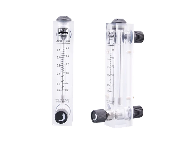
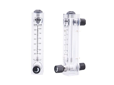
SF LZT-T/L-T series panel type flow meter is based on the LZT series and LZT-L series added regulating valve. You can adjust the flow rate. At the same time, the interface material selection of plastic PVC, with good corrosion resistance performance and low cost, is commonly used in low-pressure flow meter interfaces.
Conventional material of parts:
Technical Parameter
| Model | Range | Interface | Accuracy (±%) | ||
|---|---|---|---|---|---|
| Liquid (GPM) | Liquid (LPM) | Air (Nm3/h) | |||
| SF LZT-15T | – | 6–60 LPH, 10–100 LPH, 16–160 LPH, 25–250 LPH, 40–400 LPH | 0.1–1, 0.16–1.6, 0.25–2.5, 0.3–3, 0.4–4, 0.6–6, 1–10, 1.6–16, 2–20, 2.5–25, 3–30, 4–40, 12–120 LPM, 24–240 LPM, 48–480 LPM, 72–720 LPM | ZG1/2" M, ZG1/4" F | ±4 |
| 0.1–1 | 0.5–4 | 0.1–1, 0.16–1.6, 0.25–2.5, 0.3–3, 0.4–4, 0.6–6, 1–10, 1.6–16, 2–20, 2.5–25, 3–30, 4–40, 12–120 LPM, 24–240 LPM, 48–480 LPM, 72–720 LPM | ZG1/2" M, ZG1/4" F | ±4 | |
| 0.2–2 | 1–7 | 0.1–1, 0.16–1.6, 0.25–2.5, 0.3–3, 0.4–4, 0.6–6, 1–10, 1.6–16, 2–20, 2.5–25, 3–30, 4–40, 12–120 LPM, 24–240 LPM, 48–480 LPM, 72–720 LPM | ZG1/2" M, ZG1/4" F | ±4 | |
| 0.3–3 | 1–11 | 0.1–1, 0.16–1.6, 0.25–2.5, 0.3–3, 0.4–4, 0.6–6, 1–10, 1.6–16, 2–20, 2.5–25, 3–30, 4–40, 12–120 LPM, 24–240 LPM, 48–480 LPM, 72–720 LPM | ZG1/2" M, ZG1/4" F | ±4 | |
| 0.5–5 | 2–18 | 0.1–1, 0.16–1.6, 0.25–2.5, 0.3–3, 0.4–4, 0.6–6, 1–10, 1.6–16, 2–20, 2.5–25, 3–30, 4–40, 12–120 LPM, 24–240 LPM, 48–480 LPM, 72–720 LPM | ZG1/2" M, ZG1/4" F | ±4 | |
| SF LZT-20T | 2–10 | 10–35 | 20–100 | ZG3/4" M | ±4 |
| 4–14 | 15–50 | 20–100 | ZG3/4" M | ±4 | |
| SF LZT-25T | 2–10 | 10–35 | 20–100, 40–160, 50–250 | ZG1" M | ±4 |
| 4–14 | 15–50 | 20–100, 40–160, 50–250 | ZG1" M | ±4 | |
| 6–20 | 20–70 | 20–100, 40–160, 50–250 | ZG1" M | ±4 | |
| 10–35 | 30–130 | 20–100, 40–160, 50–250 | ZG1" M | ±4 | |
| 10–40 | 30–150 | 20–100, 40–160, 50–250 | ZG1" M | ±4 | |
| 15–45 | 50–150 | 1–10, 1.6–16, 4–40 | ZG1/2" M, NPT1/2" M | ±4 | |
| 5–45 | 50–170 | 1–10, 1.6–16, 4–40 | ZG1/2" M, NPT1/2" M | ±4 | |
| SF LZT-15L-T | 0.1–1 | 0.5–4 | 1–10, 1.6–16, 4–40 | ZG1/2" M, NPT1/2" M | ±4 |
| 0.2–2 | 0.8–8 | 1–10, 1.6–16, 4–40 | ZG1/2" M, NPT1/2" M | ±4 | |
| 0.3–3 | 1–11 | 2.5–25, 6–60, 16–80, 16–160 | ZG3/4" M, NPT3/4" M | ±4 | |
| 0.5–5 | 2–18 | 2.5–25, 6–60, 16–80, 16–160 | ZG3/4" M, NPT3/4" M | ±4 | |
| SF LZT-20L-T | 2–10 | 8–40 | 2.5–25, 6–60, 16–80, 16–160 | ZG3/4" M, NPT3/4" M | ±4 |
| 2–16 | 8–60 | 20–200, 25–250 | ZG1" M, NPT1" M | ±4 | |
| 2–20 | 8–80 | 20–200, 25–250 | ZG1" M, NPT1" M | ±4 | |
| SF LZT-25L-T | 3–13 | 10–50 | 20–200, 25–250 | ZG1" M, NPT1" M | ±4 |
| 6–24 | 20–100 | 20–200, 25–250 | ZG1" M, NPT1" M | ±4 | |
| 10–35 | 30–130 | 20–200, 25–250 | ZG1" M, NPT1" M | ±4 | |
| 10–45 | 30–170 | 20–200, 25–250 | ZG1" M, NPT1" M | ±4 | |
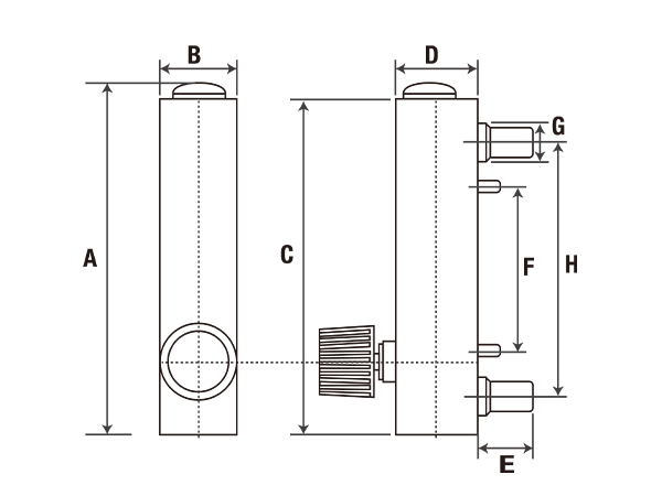
Drawings & dimension
LZT-T
| Model | Size (mm) | |||||||
|---|---|---|---|---|---|---|---|---|
| A | B | C | D | E | F | G | H | |
| SF LZT-15T | 175 | 32 | 168 | 35 | 25 | 76 | 25 | 127 |
| SF LZT-20T | 236 | 45 | 228 | 46 | 33 | 101.6 | 37 | 165 |
| SF LZT-25T | 236 | 45 | 228 | 46 | 33 | 101.6 | 37 | 165 |
LZT-L-T
| Model | Size (mm) | |||||||
|---|---|---|---|---|---|---|---|---|
| A | B | C | D | E | F | G | H | |
| SF LZT-15L-T | 216 | 32 | 206 | 37 | 33 | 1/2" | 165 | 30 |
| SF LZT-20L-T | 233 | 39 | 220 | 44 | 49 | 3/4" | 165 | 32 |
| SF LZT-25L-T | 253 | 44 | 240 | 50 | 48 | 1" | 175 | 40 |
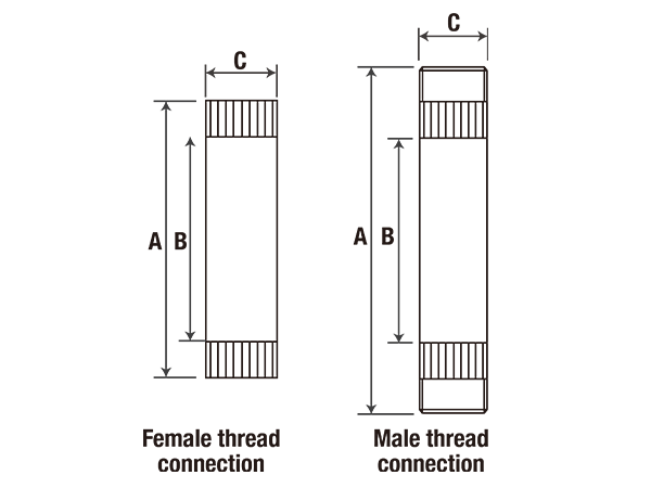
SF LZT-G/GL Series tube type flow meter is a round tube type flow meter used to measure the flow of liquid or gas in tubes. It is usually installed on the pipeline to determine the flow rate value by measuring the velocity of fluid through the pipeline, pressure difference, or other parameters.
Parts conventional material:
Technical Parameter
| Model | Range | Interface | Accuracy (±%) | ||
|---|---|---|---|---|---|
| Liquid (GPM) | Liquid (LPM) | Air (Nm3/h) | |||
| SF LZT-15G | – | 10–100 LPH, 16–160 LPH, 25–150 LPH | 0.3–3, 0.4–4, 0.6–6, 1–10, 1.6–16, 2.5–25, 4–40 | ZG1/2" F | ±4 |
| 0.05–0.5 | 0.2–2 | 0.3–3, 0.4–4, 0.6–6, 1–10, 1.6–16, 2.5–25, 4–40 | ZG1/2" F | ±4 | |
| 0.1–1 | 0.5–4 | 0.3–3, 0.4–4, 0.6–6, 1–10, 1.6–16, 2.5–25, 4–40 | ZG1/2" F | ±4 | |
| 0.2–2 | 1–7 | 0.3–3, 0.4–4, 0.6–6, 1–10, 1.6–16, 2.5–25, 4–40 | ZG1/2" F | ±4 | |
| 0.3–3 | 1–11 | 0.3–3, 0.4–4, 0.6–6, 1–10, 1.6–16, 2.5–25, 4–40 | ZG1/2" F | ±4 | |
| 0.5–5 | 2–18 | 0.3–3, 0.4–4, 0.6–6, 1–10, 1.6–16, 2.5–25, 4–40 | ZG1/2" F | ±4 | |
| SF LZT-20G | 1–10 | 5–35 | 6–60, 10–100, 15–140 | ZG3/4" F | ±4 |
| 2–16 | 10–60 | 6–60, 10–100, 15–140 | ZG3/4" F | ±4 | |
| 2–20 | 10–70 | 6–60, 10–100, 15–140 | ZG3/4" F | ±4 | |
| SF LZT-25G | 1–10 | 5–35 | 6–60, 10–100, 15–140, 16–160, 25–250, 30–300 | ZG1" F | ±4 |
| 2–16 | 10–60 | 6–60, 10–100, 15–140, 16–160, 25–250, 30–300 | ZG1" F | ±4 | |
| 2–20 | 10–70 | 6–60, 10–100, 15–140, 16–160, 25–250, 30–300 | ZG1" F | ±4 | |
| 2–25 | 10–100 | 6–60, 10–100, 15–140, 16–160, 25–250, 30–300 | ZG1" F | ±4 | |
| 3–30 | 12–120 | 6–60, 10–100, 15–140, 16–160, 25–250, 30–300 | ZG1" F | ±4 | |
| 4–40 | 15–150 | 6–60, 10–100, 15–140, 16–160, 25–250, 30–300 | ZG1" F | ±4 | |
| 5–45 | 20–170 | 6–60, 10–100, 15–140, 16–160, 25–250, 30–300 | ZG1" F | ±4 | |
| SF LZT-40G | 4–40 | 15–150 | 35–350, 150–400, 150–500, 120–600, 150–700 | ZG1-1/2" M, ZG1-1/2" F | ±4 |
| 5–45 | 20–170 | 35–350, 150–400, 150–500, 120–600, 150–700 | ZG1-1/2" M, ZG1-1/2" F | ±4 | |
| 6–60 | 20–220 | 35–350, 150–400, 150–500, 120–600, 150–700 | ZG1-1/2" M, ZG1-1/2" F | ±4 | |
| 8–80 | 30–300 | 35–350, 150–400, 150–500, 120–600, 150–700 | ZG1-1/2" M, ZG1-1/2" F | ±4 | |
| 10–100 | 40–400 | 35–350, 150–400, 150–500, 120–600, 150–700 | ZG1-1/2" M, ZG1-1/2" F | ±4 | |
| SF LZT-50G | 20–80 | 50–300 | 120–600, 300–850, 400–1,200, 500–1,400 | ZG2" F | ±4 |
| 20–100 | 75–400 | 120–600, 300–850, 400–1,200, 500–1,400 | ZG2" F | ±4 | |
| 40–120 | 150–450 | 120–600, 300–850, 400–1,200, 500–1,400 | ZG2" F | ±4 | |
| 50–150 | 150–600 | 120–600, 300–850, 400–1,200, 500–1,400 | ZG2" M | ±4 | |
| 50–200 | 200–800 | 120–600, 300–850, 400–1,200, 500–1,400 | ZG2" M | ±4 | |
| SF LZT-75G | 50–300 | 200–1000 | – | ZG3" F, ZG3" M | ±4 |
| 50–400 | 200–1500 | – | ZG3" F, ZG3" M | ±4 | |
| SF LZT-15GL | – | 10–100 LPH, 16–160 LPH, 25–150 LPH | 0.1–1, 0.3–3, 0.6–6, 1–10, 1.6–16, 2.5–25, 4–40 | ZG1/2" F | ±4 |
| 0.05–0.5 | 0.2–2 | 0.3–3, 0.4–4, 0.6–6, 1–10, 1.6–16, 2.5–25, 4–40 | ZG1/2" F | ±4 | |
| 0.1–1 | 0.5–4 | 0.3–3, 0.4–4, 0.6–6, 1–10, 1.6–16, 2.5–25, 4–40 | ZG1/2" F | ±4 | |
| 0.2–2 | 1–7 | 0.3–3, 0.4–4, 0.6–6, 1–10, 1.6–16, 2.5–25, 4–40 | ZG1/2" F | ±4 | |
| 0.3–3 | 1–11 | 0.3–3, 0.4–4, 0.6–6, 1–10, 1.6–16, 2.5–25, 4–40 | ZG1/2" F | ±4 | |
| 0.5–5 | 2–18 | 0.3–3, 0.4–4, 0.6–6, 1–10, 1.6–16, 2.5–25, 4–40 | ZG1/2" F | ±4 | |
| SF LZT-20GL | 1–10 | 5–35 | 6–60, 10–100, 15–140 | ZG3/4" F | ±4 |
| 2–16 | 10–60 | 6–60, 10–100, 15–140 | ZG3/4" F | ±4 | |
| 2–20 | 10–70 | 6–60, 10–100, 15–140 | ZG3/4" F | ±4 | |
| SF LZT-25GL | 1–10 | 5–35 | 6–60, 10–100, 15–140, 16–160, 25–250, 30–300 | ZG1" F | ±4 |
| 2–16 | 10–60 | 6–60, 10–100, 15–140, 16–160, 25–250, 30–300 | ZG1" F | ±4 | |
| 2–20 | 10–70 | 6–60, 10–100, 15–140, 16–160, 25–250, 30–300 | ZG1" F | ±4 | |
| 3–30 | 12–120 | 6–60, 10–100, 15–140, 16–160, 25–250, 30–300 | ZG1" F | ±4 | |
| 4–40 | 15–150 | 6–60, 10–100, 15–140, 16–160, 25–250, 30–300 | ZG1" F | ±4 | |
| 5–45 | 20–170 | 6–60, 10–100, 15–140, 16–160, 25–250, 30–300 | ZG1" F | ±4 | |
| SF LZT-40GL | 1–10 | 5–35 | 6–60, 10–100, 15–140, 16–160, 25–250, 30–300, 35–350, 40–400, 50–500 | ZG1-1/2" M | ±4 |
| 2–16 | 10–60 | 6–60, 10–100, 15–140, 16–160, 25–250, 30–300, 35–350, 40–400, 50–500 | ZG1-1/2" M, ZG1-1/2" F | ±4 | |
| 2–20 | 10–70 | 6–60, 10–100, 15–140, 16–160, 25–250, 30–300, 35–350, 40–400, 50–500 | ZG1-1/2" M, ZG1-1/2" F | ±4 | |
| 3–30 | 12–120 | 6–60, 10–100, 15–140, 16–160, 25–250, 30–300, 35–350, 40–400, 50–500 | ZG1-1/2" M, ZG1-1/2" F | ±4 | |
| 4–40 | 15–150 | 6–60, 10–100, 15–140, 16–160, 25–250, 30–300, 35–350, 40–400, 50–500 | ZG1-1/2" M, ZG1-1/2" F | ±4 | |
| 5–45 | 20–170 | 6–60, 10–100, 15–140, 16–160, 25–250, 30–300, 35–350, 40–400, 50–500 | ZG1-1/2" M, ZG1-1/2" F | ±4 | |
| 6–60 | 20–220 | 6–60, 10–100, 15–140, 16–160, 25–250, 30–300, 35–350, 40–400, 50–500 | ZG1-1/2" M, ZG1-1/2" F | ±4 | |
Technical Parameter
| Model | Size (mm) | ||
|---|---|---|---|
| A | B | C | |
| SF LZT-15G | 210 | 160 | φ32 |
| SF LZT-20G | 278 | 210 | φ45 |
| SF LZT-25G | 278/306 | 210/235 | φ45/φ51 |
| SF LZT-40G | 302 | 230 | Φ68 |
| SF LZT-50G | 340/380 | 270 | φ75 |
| SF LZT-75G | 400 | 290 | φ100 |
| SF LZT-15GL | 210 | 180 | φ32 |
| SF LZT-20GL | 278 | 236 | φ45 |
| SF LZT-25GL | 265 | 235 | φ51 |
| SF LZT-40GL | 306 | 235 | φ51 |
Here are product catalogue and data sheet for your reference. more information just contact us.


Hengshui Snowate Environmental Technology Co., Ltd. (Snowate) aims to become a solution-oriented company to promote the sustainable development of water.