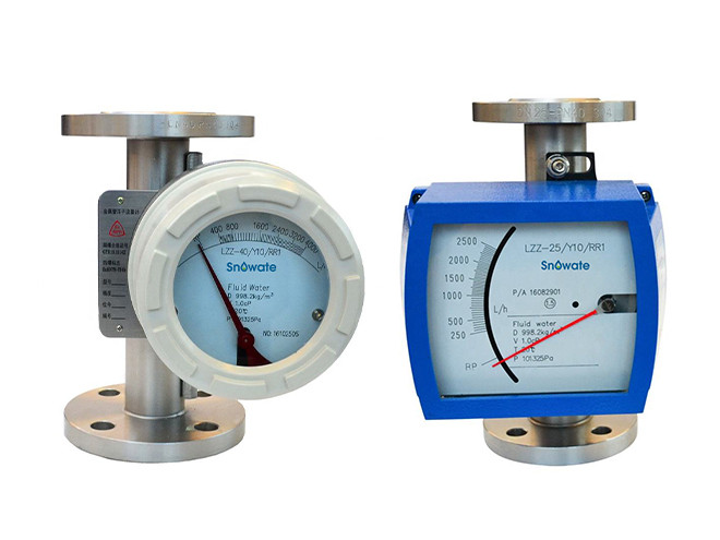
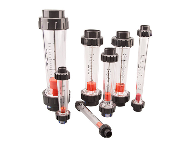
Two different types of SVF LZ series metallic tube variable area flow meter

SVF LZ Series Metallic Tube Variable Area Flow Meter Transmits Flow via Magnetic Coupling Drive System

The SVF LZ-Series metallic tube variable area flow meter is a flow measuring instrument used for measuring the instantaneous flow rate and cumulative flow of fluids (liquids, gases, and steam) through a closed conduit. It can provide local indication as well as transmit signals remotely.

This flow meter is widely used in various industries such as petroleum, chemical, water treatment, food, pharmaceutical, papermaking, and others due to its simple structure, ease of maintenance, and long service life.

If the fluid contains ferromagnetic particles, a magnetic filter should be installed at the entrance of the flow meter. If the inlet flow (pressure) of the flow meter is unstable, a damping device manufactured with high technology may be installed on the measuring component to ensure long-term stable and reliable use for the measurement of clean gases.

  • Specifications
  • Working Principle
  • Structure
  • Video
Specification

Technical Parameter

Measure Range Water (20°C): 2.5–150000 L/h, Air (20°C, 101325 Pa): 0.07–3000 Nm3/h
Range Ratio 10:1
Accuracy Grade 1.5, 2.5
Fluid Working Pressure DN15–DN50: 4.0 MPa, DN80–DN150: 1.6 MPa
Working Pressure of Coating 1.6 MPa
Fluid Working Temperature -80 °C to 200 °C (PTFE ≤ +85 °C), high temperature type ≤ 400 °C
Connection Type Flange connection, Thread connection or Tri-clamp connection flange refer to standard GB/T9119; ANSI 150Ibs, 300Ibs; HG20592–20635; Other standard flange can be made to the user requirement.
Environment Temperature -25 °C to +55 °C
Medium Viscosity DN15 ≤ 5 mPa.S; DN25–DN100 ≤ 250 mPa.S
Electricity Signal Output Output Signal: (4–20 mA), Linear Accuracy: 0.5%, Temperature influence: 0.5% / 10 °C, Power Supply: (13–30) V DC, Power Supply Consume: ≤ 250 mW
Restrict Alarm Power Supply:24 (10%) V DC, Power Loss: ≤ 3W, Working Temperature:-25 °C to +60 °C
Explosion-Proof Grade Ex lb II CT5

Flow Rate Reference

Read MoreRead Less
Table 1: SVF LZ Series Metallic Tube Variable Area Flow Meter Flow Rate Reference
Nominal Diameter (mm) Water 20 °C 101325 Pa (L/h) Air 20 °C 101325 Pa (m3/h) Maximum Pressure Loss (kPa) Accuracy (±%) Working Pressure (MPa)
RRO, RR1, RL PTFE RRO、RR1、RL RRO, RR1, RL PTFE
15 1.6–16 0.05–0.5 6.5 ±1.5 ≤4.0
15 2.5–25 0.07–0.7 6.5 ±1.5 ≤4.0
15 4–40 2.5–25 0.12–1.2 6.5 5.5 ±1.5 ≤4.0
15 6–60 4–40 0.18–1.8 6.6 5.5 ±1.5 ≤4.0
15 10–100 6–60 0.3–3 6.6 5.6 ±1.5 ≤4.0
15 16–160 10–100 0.4–4 6.8 5.8 ±1.5 ≤4.0
15 25–250 16–160 0.7–7 7.2 6.1 ±1.5 ≤4.0
15 40–400 25–250 1.0–10 8.6 6.1 ±1.5 ≤4.0
15 60–600 40–400 1.5–15 11.1 7.3 ±1.5 ≤4.0
15 80–800 60–600 2.5–25 11.1 7.3 ±1.5 ≤4.0
15 100-1000 80–800 3.0–30 11.1 7.3 ±1.5 ≤4.0
20 40–400 40–400 0.75–7.5 8.6 6.1 ±1.5 ≤4.0
20 60–600 60–600 1.2–12 11.1 7.3 ±1.5 ≤4.0
20 100–1000 100–1000 1.8–18 11.1 7.3 ±1.5 ≤4.0
25 40–400 40–400 1.0–10 6.5 5.9 ±1.5 ≤4.0
25 60–600 50–500 1.5–15 6.5 6.2 ±1.5 ≤4.0
25 80–800 60–600 2.5–25 7 7 ±1.5 ≤4.0
25 100–1000 80–800 4–40 7 5.9 ±1.5 ≤4.0
25 160–1600 100–1000 5–50 8 6 ±1.5 ≤4.0
25 250–2500 160–1600 6–60 10.8 6.8 ±1.5 ≤4.0
25 400–4000 250–2500 8–80 15.8 9.2 ±1.5 ≤4.0
25 500–5000 400–4000 10–100 16.2 11 ±1.5 ≤4.0
25 600–6000 500–5000 15–150 16.5 12 ±1.5 ≤4.0
32 160–1600 160–1600 3–30 8 6 ±1.5 ≤4.0
32 250–2500 250–2500 5–50 10.8 6.8 ±1.5 ≤4.0
32 400–4000 400–4000 7.5–75 15.8 9.2 ±1.5 ≤4.0
32 600–6000 600–6000 16.5 12 ±1.5 ≤4.0
40 400–4000 400–4000 3–30 8 6.5 ±1.5 ≤4.0
40 600–6000 600–6000 5–50 11 6.8 ±1.5 ≤4.0
40 1000–10000 1000–10000 7.5–75 16.2 9.4 ±1.5 ≤4.0
50 600–6000 400–4000 18–180 8 6.5 ±1.5 ≤4.0
50 1000–10000 600–6000 25–250 11 6.8 ±1.5 ≤4.0
50 1600–16000 1000–10000 40–400 16.2 9.4 ±1.5 ≤4.0
50 2000–20000 1600–16000 50–500 17 14.5 ±1.5 ≤4.0
50 2500–25000 2000–20000 60–600 19 16.5 ±1.5 ≤4.0
65 1200–12000 1200–12000 18–180 8.2 6.9 ±1.5 ≤1.6
65 1600–16000 1600–16000 30–300 8.2 6.9 ±1.5 ≤1.6
65 2500–25000 2500–25000 37–370 15.5 11.9 ±1.5 ≤1.6
80 1600–16000 1000–10000 50–500 8.2 6.9 ±1.5 ≤1.6
80 2500–25000 1600–16000 60–600 15.5 11.9 ±1.5 ≤1.6
80 4000–40000 2000–20000 100–1000 20 16.1 ±1.5 ≤1.6
80 5000–50000 2500–25000 150–1500 25 18.1 ±1.5 ≤1.6
100 4000–40000 2000–20000 100–1000 8.4 8.1 ±1.5 ≤1.6
100 5000–50000 2500–25000 150–1500 11.2 9.1 ±1.5 ≤1.6
100 6000–60000 4000–40000 180–1800 20 16.5 ±1.5 ≤1.6
100 8000–80000 5000–50000 240–2400 25.4 22.2 ±1.5 ≤1.6
100 10000–100000 8000–80000 300–3000 32 29.2 ±1.5 ≤1.6
125 10000–100000 8000–80000 300–3000 42 38.5 ±1.5 ≤1.6
125 25000–125000 10000–100000 45 42 ±1.5 ≤1.6
150 12500–125000 10000–100000 45 42 ±1.5 ≤1.6
150 15000–150000 12500–125000 60 58 ±1.5 ≤1.6
Note:
  • To ensure variable-area flow meter working stability,it should be assured that working pressure not less than double of max loss of pressure when
  • flow meter used to measure liquid; when you measured medium is air, it should be assured that working pressure not less than five times of
  • max loss of pressure;
  • Above measuring range is for reference only, you can select other measuring ranges according to range ratio 10:1;
Flow meter can be special made for you as per medium density, viscosity, temperature, pressure and other parameters you supply.

Drawings & dimensions

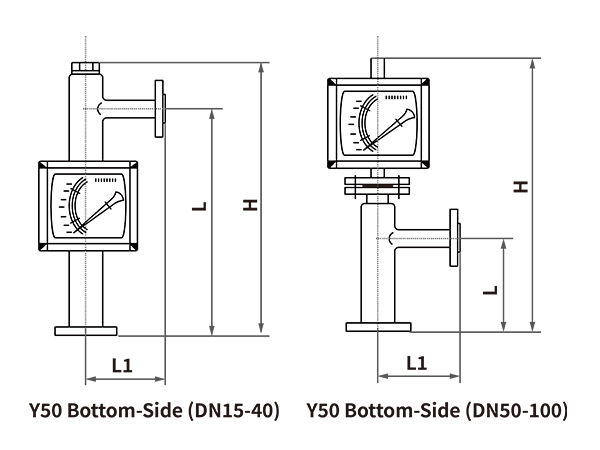
A dimension drawing of bottom-in side-out SVF LZ series metallic tube variable area flow meter.
Table 2: SVF LZ Series Flow Meter Dimensions – Bottom in Side Out
DN H (mm) L (mm) L1 (mm)
15 350 250 120
20 350 250 120
25 350 250 120
32 350 250 120
40 350 250 120
50 600 250 120
65 600 250 120
80 700 250 150
100 700 250 150
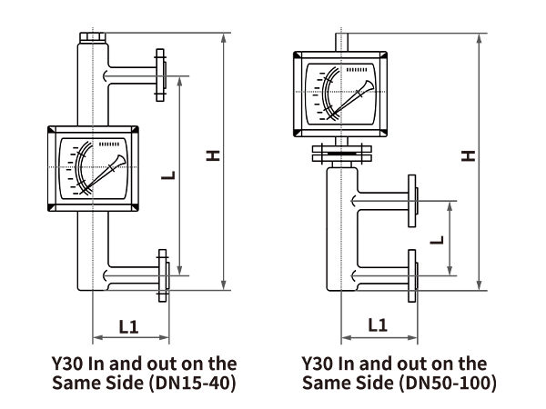
A dimension drawing of side-in side-out SVF LZ series metallic tube variable area flow meter.
Table 3: SVF LZ Series Flow Meter Dimensions – Side in Side Out
DN H (mm) L (mm) L1 (mm)
15 500 250 120
20 500 250 120
25 500 250 120
32 500 250 120
40 500 250 120
50 650 250 120
65 650 250 120
80 800 300 150
100 800 300 150
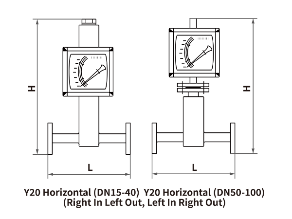
A dimension drawing of horizontal SVF LZ series metallic tube variable area flow meter.
Table 4: SVF LZ Series Flow Meter Dimensions – Horizontal
DN H (mm) L (mm)
15 430 250
20 430 250
25 450 250
32 450 250
40 450 250
50 540 350
65 540 350
80 540 400
100 540 400
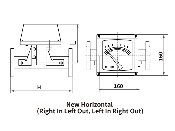
A dimension drawing of new horizontal SVF LZ series metallic tube variable area flow meter.
Table 5: SVF LZ Series Flow Meter Dimensions – New Horizontal
DN H (mm) L (mm)
15 250 160
20 250 160
25 250 160
32 250 160
40 250 160
50 250 160
65 250 160
80 250 160
100 300 160
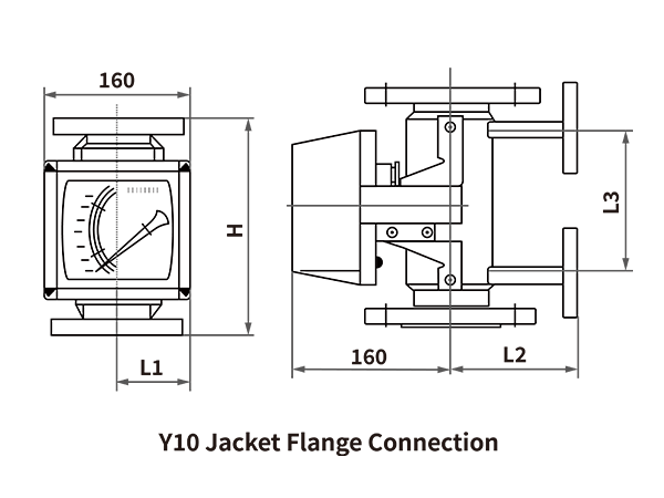
A dimension drawing of jacket flange connection SVF LZ series metallic tube variable area flow meter.
Table 6: SVF LZ Series Flow Meter Dimensions – Jacket Flange
DN H (mm) L1 (mm) L2 (mm) L3 (mm)
15 250 84 116 150
20 250 84 116 150
25 250 95 128 150
32 250 99 132 150
40 250 99 132 150
50 250 111 144 150
65 250 111 144 150
80 250 130 183 150
100 250 146 179 150
Working Principle
Structure
Videos
Downloads

Here are product catalogue and data sheet for your reference. more information just contact us.

The nuonuo is answering the phone.
Interested?