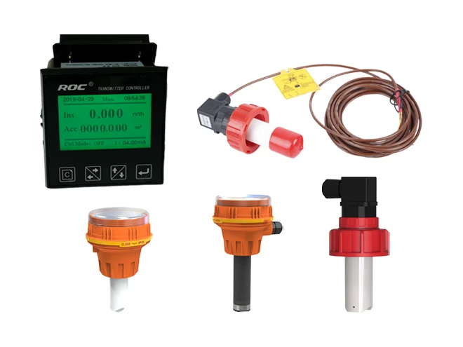
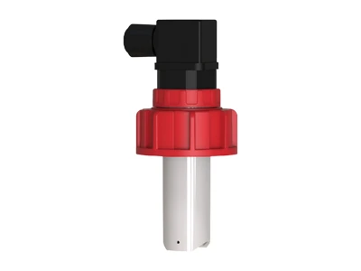
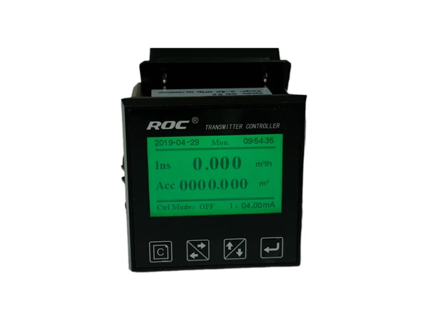
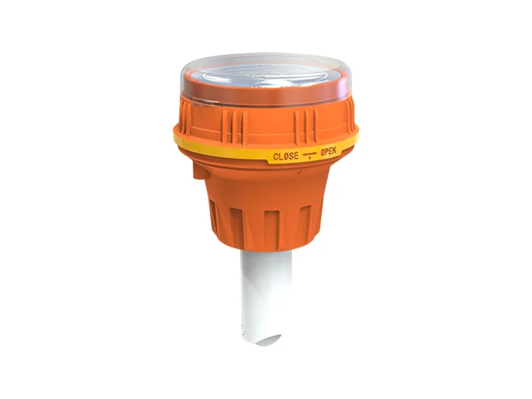
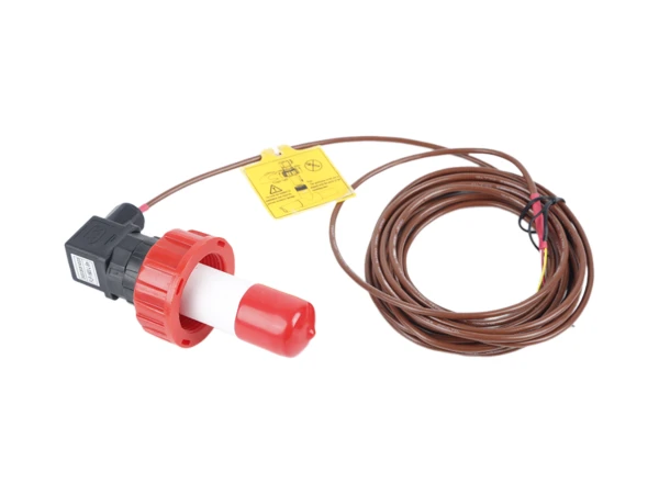
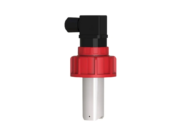
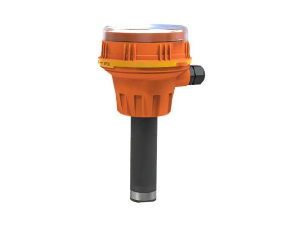
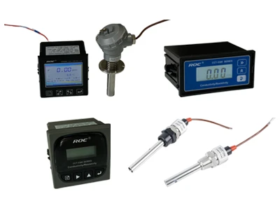
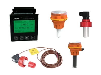
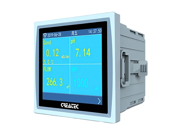
Paddle wheel flow online controller and paddle wheel flow senor

Paddle Wheel Flow Instrument for Industrial Automation Systems

The paddle wheel flow instrument is a device that integrates an impeller flow sensor and flow controller. It is widely used in industrial automation systems that require precise fluid flow control, such as chemical, food processing, water treatment, and pharmaceutical industries. This device provides a reliable solution for modern industrial fluid management through high automation and precise control.

  • Specification
  • Working Principle
  • Video
Specification
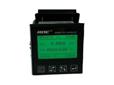
  • A FCT-8350 flow meter

    FCT-8350 Flow Meter

  • A FCT-8920 flow transmitter

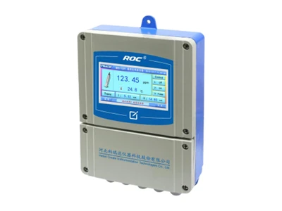
    FCT-8920 Flow Transmitter

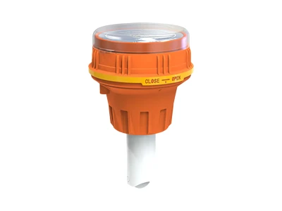
  • A FLP-1600-L paddle wheel flow sensor

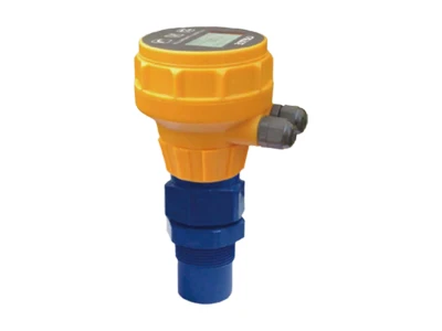
    FLP-1600-L Paddle Wheel Flow Sensor

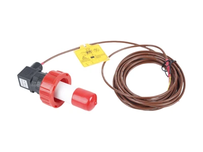
  • A FLP-1600-LD digital flow sensor

    FLP-1600-LD Digital Flow Sensor

  • A FET-8920 insert electromagnetic flow meter

    FET-8920 Insert Electromagnetic Flow Meter

  • K coefficient and standard diameter/non-standard diameter can be adjusted in a flexible and convenient way.
  • Different kinds of the engineer working load could be chosen, it can meet the measurement standards of different country and region.
  • (Instantaneous flow high/low limit alarm, instantaneous flow frequency) multiple alarm settings.
  • The frequency pulse of instantaneous flow rate, direct sensor pulse integrating volume frequency division, integrating volume pulse and many kinds of control mode for selection.
  • To start the poly line modification for the measurements to provide better precision correction.
  • Compatible with tangential type/axial type pulse sensor.
  • Small signal cutting and small signal correction function, to meet the operation compensation under low flow rate condition.
  • 3.5 inch screen, Multi-parameter display and Chinese/English for selection, Heuristic operation.
  • Semiconductor photoelectric relay (non contact), switch control/proportional pulse control.
  • It can achieve the ratio of flow parameter pulse pharmacy dosing.
  • Measurement/control/transmission each unit can complete electrical isolated, each other without any interference.
  • Can program Current transmitting between any two points in whole flow range.
  • Isolated (4–20)mA current loop, instrument/Transmitter for selection.
  • EMC design with better ability on anti-interference.
  • Meeting High humidity site safety power supply regulation, DC 24V with standard.
A FCT-8350 flow meter

Main Technical Data

Table 1: FCT-8350 Flow Meter Main Technical Data
Measurement Range Instantaneous flow: (0–2000) m3/h
Accumulated flow: (0–99999999) m3
Flow Rate (0–5) m/s
Applicable Pipe Diameter DN25–DN1000 for selection
Resolution 0.001 m3/h
Renew Interval 1s
Accuracy 2.0 level
Repeatability ±0.5%
Probe Input Range: 0.5Hz–2KHz
Power Supply: DC 12V (instrument supply)
Analog Output (4–20)mA, Instrument/Transmitter for selection
Control Output Semi-conductor photo electronic relay, Load current: 50 mA (max) AC/DC 30V
Control Mode Instantaneous flow high/low limit alarm, flow variable frequency conversion
Probe pulse frequency division, integrating value pulse, control on/off function
Working Power DC 24V
Power Consumption ≤ 3.0W
Cable Length 5m as standard or (1–500) m for selection
Working Environment Temp.: (0–50) °C
Relative Humidity: ≤ 85% RH (non condensation)
Storage Environment Temp.: (-20 to +60) °C
Relative Humidity: ≤ 85% RH (non condensation)
Protection Level IP65 (with back cover)
Dimension (H × W × D) 96 mm × 96 mm × 94 mm
Hole Size (H × W) 91 mm × 91 mm
Installation Panel mounted, fast installation

Application

Widely used for online measurement of acid & alkali in low concentrations and the low viscosity single-phase fluid of non-trade settlement process.

  • Various setting ways of coefficient K and standard pipe diameter/non-standard pipe diameter.
  • A variety of engineering units can be chose to meet measurement standards of different countries and areas.
  • Internal optional (4–20)mA analog signal, instrument/transmitting dual-mode/RS485 digital communication.
  • Programming current transmitting between any two points in the range of whole velocity.
  • Flow alarm, flow frequency conversion, impeller pulse frequency division, integrating volume pulse, a variety of control mode selection.
  • DC 24V centralized power supply, transmitter non-polarity connection, internal automatic identification.
  • Good electromagnetic compatibility (EMC) design, compatible with complex electromagnetic environment of industrial field.
A FCT-8920 flow transmitter

Main Technical Data

Table 2: FCT-8920 Flow Transmitter Main Technical Data
Measurement Range Instantaneous flow (0–2000) m3/h
Accumulative flow (0–99999999) m3
Flow rate (0–5) m/s
Resolution 0.001 m3/h
Refresh Rate 1 s
Accuracy Grade Grade 2.0
Repeatability ±0.5%
(4~20)mA Output Number of channels Single channel
Technical features Isolation, inversion, adjustable, instrument/transmitting dual mode
Loop resistance 300Ω (Max), DC 24V
Transmission accuracy ±0.1 mA
Control Output Number of channels Single channel
Electrical contact Semiconductor photoelectric relay
Load capacity 50mA (Max), AC/DC 30V
Control mode Upper/lower limit alarm of instantaneous flow, integrating amount/pulse, instantaneous flow frequency conversion, impeller pulse frequency division
Digital Output RS485 (MODBUS protocol)
Working Power Source Power supply DC 24V±4V
Power consumption ≤ 3.0W
Applicable pipe diameter DN25–DN350(otherwise agreed about large pipe diameter)
Working Environment Temperature: (0–50) °C
Relative Humidity: ≤ 85% RH (none condensation)
Storage Environment Temperature: (-20 to +60) °C
Relative Humidity: ≤ 85% RH (none condensation)
Protection Grade IP65
Installation Method Plug-in pipe line installation

Application

Widely use in Water pipeline in industrial process, Single-phase fluid with low viscosity. Acid and alkali liquid with low concentration, non-trade settlement process measurement and control.

Widely used for measuring and calculating of flow volume and flow speed of municipal water, cooling water, pure water, high-pure water, the no stringiness impurity wastewater, the low-stickiness liquid.

Main Technical Data

  • Material: Engineering plastic
  • Installation method: Upright installation, fixed by screwing
  • Medium temperature: 0-60 °C
  • Storage temperature: -20 to +70 °C
  • Proof pressure: 0.6 MPa
  • Power supply: DC 12V
  • Output impulse value: High level ≥ 8V
  • Transferring distance (sensor to meter): ≤ 1000m
  • Applied pipe diameter: DN25-DN350
  • Pipe material: Plastic, metal, glass fiber reinforced plastic, cement
  • Required circumstances: No strong disturbance of variation magnetic field around the sensor
  • Required water quality: Install a filter at the upward position if there are big granules and fiber in the pipe
A FLP-1600-L paddle wheel flow sensor

Application

Widely used for measuring and calculating of flow volume and flow speed of municipal water, cooling water, pure water, high-pure water, the no stringiness impurity wastewater, the low-stickiness liquid.

  • Measurement/Communication integrated Paddle Wheel flow sensor
  • Design the flow meter function inside the sensor directly using RS485 digital physical port (Modbus RTU protocol)
  • Directly output the instantaneous and accumulated flow data, without any need for analog-digital conversion
  • Setting K factor, Address, and baud rate using PC software
  • Pre-measuring unit with high integrated design and high anti-interference ability
  • Can connect with a computer, configuration system, PLC, wireless modules
  • Meet the demand of system completion in the Internet Age
A FLP-1600-LD digital flow sensor

Main Technical Data

Table 3: FLP-1600-LD Digital Flow Sensor Main Technical Data
Measure Range Flow rate (0.5–5) m/s
instantaneous (0–2000) m3/h
accumulated (0–99999999) m3
Accuracy 0.001 m3/h
Accuracy Level 2.0 level
Repeatability ±0.5%
Sensor Output RS485 (Standard Modbus RTU protocol)
Power Supply DC 24V±4V, Consumption: < 1.0W
Cable Length Standard 10 m, optional: (1–1000) m
Storage Environment Temp.: (-20 to +60)°C
Humidity: ≤ 90% RH (Non-condensing)
Protect Level IP65
Dimension Size The out circle 57 mm, length: 130 mm
Main Body Material Industrial plastic
Flow Rate Range (0.5–5) m/s
Max Pressure ≤ 0.6 MPa
Installation Mode Vertical mounting, tangential measurement
  • Engineering units can be selected, standard pipe diameter/non-standard pipe diameter can be set.
  • Internal optional (4–20) mA analog signal, meter/transmission dual mode/RS485 digital communication and pulse output, with perfect flow alarm control function.
  • Integrated tangential measurement and installation accessories are abundant and easy to construct.
  • DC 9–28V power supply, non-polarity connection, and internal automatic identification.
A FET-8920 insert electromagnetic flow meter

Main Technical Data

Table 4: FET-8920 Insert Electromagnetic Flow Meter Main Technical Data
Measurement Range Instantaneous flow (0–2000) m3/h
Accumulative flow (0–99999999) m3
Flow rate (0.5–5) m/s
Resolution 0.001 m3/h
Accuracy Level Less than 2.5% RS or 0.025 m/s. whichever is the largest
Conductivity > 20 μS/cm
(4-20)mA Output Number of channels Single channel
Technical features Isolated, reversible, adjustable, meter/transmission dual mode
Loop resistance 400Ω (Max), DC 24V
Transmission accuracy ±0.1mA
Control Output Number of channels Single channel
Electrical contact Semiconductor photoelectric relay
Load capacity 50mA (Max), DC 30V
Control mode Instantaneous amount upper/ lower limit alarm
Digital Output RS485 (MODBUS protocol), Impulse output 1KHz
Working Power Source Power supply DC 9-28V
Power consumption ≤ 3.0W
Diameter DN40–DN300 (can be customized)
Working Environment Temperature: (0–50) °C
Relative Humidity: ≤ 85% RH (none condensation)
Storage Environment Temperature: (-20 to +60)°C
Relative Humidity: ≤ 85% RH (none condensation)
Protection Grade IP65
Installation Method Insertion pipeline installation
Working Principle
Paddle wheel flow instrument working principle diagram

The working principle of a paddle wheel flow instrument is essentially a closed-loop control system. As fluid flows through the pipe, it drives the paddle wheel to rotate. The sensor detects the rotation speed of the paddle wheel and converts it into an electrical signal, which is then calculated to obtain the flow rate. The controller receives the flow rate data and compares it with the preset target flow rate. If it detects that the flow rate deviates from the set value, the control unit will adjust the operation of the control valve or pump to increase or decrease the fluid flow rate. The adjusted flow rate is then detected by the sensor again, forming a continuous feedback loop to ensure the stability and accuracy of the flow rate.

Videos
Downloads

Here are product catalogue and data sheet for your reference. more information just contact us.

The nuonuo is answering the phone.
Interested?