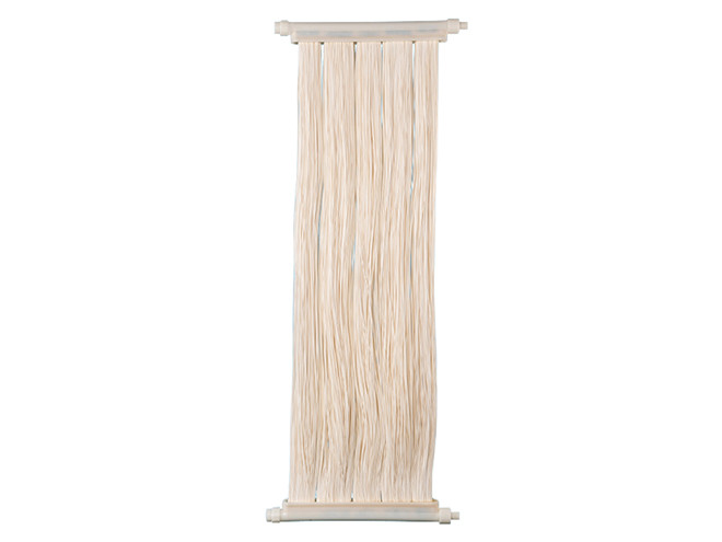
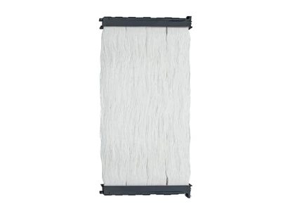
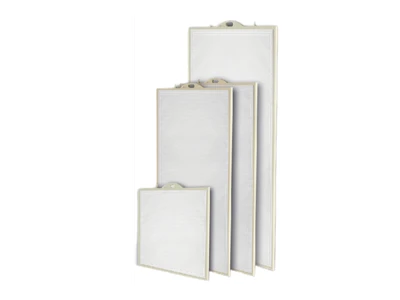
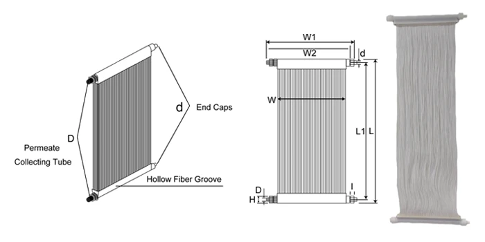
A group of MBR membranes arranged vertically

Overview of MBR Membrane Technology

MBR membrane , as a type of microfiltration membrane, can effectively remove pollutants such as suspended solids and microorganisms from wastewater, producing high-quality purified water. It is widely used in wastewater treatment, industrial wastewater treatment, and water resource recovery, offering excellent water purification performance and space-saving advantages.

Our MBR membranes are made of hollow fiber PVDF membrane with high tensile strength and excellent chemical corrosion resistance. The 0.1 μm pore size provides excellent rejection of suspended solids, bacteria, and viruses. Compared with conventional treatment, SWB MBR modules produce extremely high quality permeate. Due to the high mixed liquor suspended solids (MLSS), SWB MBR modules can greatly reduce the overall treatment plant footprint and annual operation cost.

  • Specification
  • Features
  • Working Principle
  • Videos
Specification
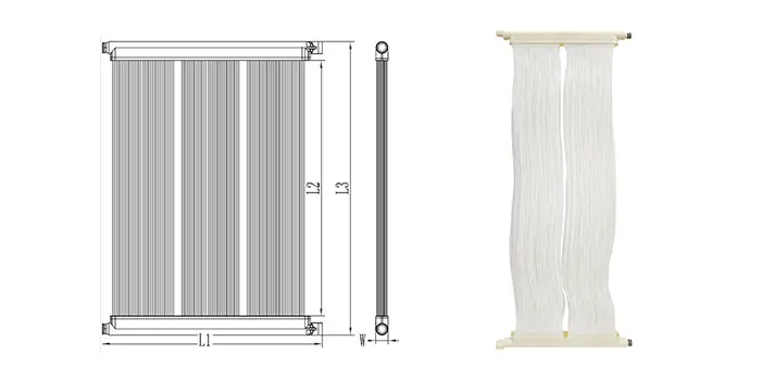
  • A SWB1V series MBR membrane

    SWB1V Series Modules

  • A SWB3V series MBR membrane

    SWB3V Series Module

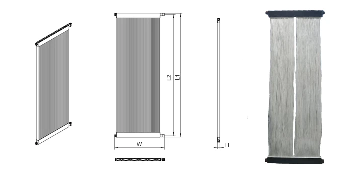
  • A SWBT series MBR membrane

    SWBT Series Module

  • A SWBFT series MBR membrane

    SWBFT Series Module

SWB1V MBR modules are made with reinforced hollow fiber PVDF membrane. The hollow fibers have high tensile strength with excellent chemical resistance. 0.1μm pore size provides superior rejection rate of suspended solids, bacteria and viruses.Compared with conventional treatment, SWB1V MBR modules produce extremely high quality permeate.Due to the high mixed liquor suspended solids (MLSS), SWB1V MBR modules can greatly reduce the overall treatment plant footprint and annual operation cost.

*Equivalent modules can be customized on customers' request.

A SWB1V series MBR membrane

Specifications

Annotated SWFSFT series MBR membrane drawing
Read MoreRead Less
Table 1: SWB1V4024-10/SWB1V6024-15/SWB1V7924-20
Module Model SWB1V4024-10 SWB1V6024-15 SWB1V7924-20
Effective Membrane Area (m2/ft2) 10/107.64 15/161.46 20/215.28
Membrane Material PVDF (with PET supporting layer)
Pore Size (μm) 0.1
Fiber I.D./O.D. (mm/inch) 1.1 / 2.2
L1 (mm/inch) 1,000/39.37 1,500/59.05 2,000/78.74
L (mm/inch) 1,025/40.35 1,525/60.04 2,025/79.72
W (mm/inch) 480/18.9 480/18.9 480/18.9
W1 (mm/inch) 620/24.4 620/24.4 620/24.4
W2 (mm/inch) 591.7/23.30 591.7/23.30 591.7/23.30
I (mm/inch) 28.3/1.11 28.3/1.11 28.3/1.11
H (mm/inch) 48/1.89 48/1.89 48/1.89
Permeate Port D DN20
End Cap Size d (mm) φ24
Filtration Mode Suction with negative pressure
Design Flux (LMH) 10–30
Module Gross Weight (kg/lb) 4.7/10.36 5.8/12.79 6.6/14.55
Sealing Material PU
Permeate Collecting Tube Material ABS
Recommended Flux (L/H) 100–300 150–450 250–750
Max.△TMP (Mpa/psi) -0.05/-7.25
Operation Temp. Range (°C/°F) 5–40 / 41–104
Optimal Operation pH Range 6–9
Recommended pH Range 2–10
Max.Active Chlorine (ppm) 1,000
Permeate Turbidity (NTU) ≤ 0.5
Permeate SS (mg/L) ≤ 5
Annotated SWB1VP series MR membrane drawing
Read MoreRead Less
Table 2: SWB1V4024-10P/SWB1V6022-15P/SWB1V7924-20P
Module Model SWB1V4024-10P SWB1V6022-15P SWB1V7924-20P
Effective Membrane Area (m2/ft2) 10 15 20
Membrane Material PVDF (with PET Supporting Layer)
Pore Size (μm) 0.1
Fiber O.D. (mm) 2.2
L1 (mm) 610 570 610
L2 (mm) 950 1450 1950
L3 (mm) 1025 1525 2025
W (mm) 46 46 46
Connector φ27 φ27 φ27
Filtration Mode Suction with Negative Pressure
Recommended TMP (Kpa) 0–35
Maximum backwash pressure (Kpa) 70
Design Flux (L/m2.h, 25 °C) 15–30
Backwash Flux (L/m2.h) 20–50
Operation Temp. Range (°C) 5–45
Recommended pH Range 2–10
Aeration (Nm3/m2.h) Pulse Aeration: 50–75, Perforated aeration: 80–120
Chemical Cleaning pH Range 1–12
Maximum NaClO Tolerance Concentration (mg/L) 3000
Permeate Turbidity (NTU) ≤ 0.8
Permeate SS (mg/L) ≤ 5.0
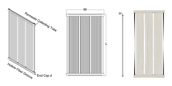
Annotated SWFSFK series MR membrane drawing
Read MoreRead Less
Table 3: SWB1V8032-30
Module Model SWB1V8032-30
Membrane Surface Areas (m2/ft2) 30/322.92
Hollow Fiber Material PVDF (with PET supporting layer)
Pore Size (μm) 0.1
I.D. / O.D (mm/inch) 1.1 / 2.2
Flow Direction Outside-in
L1 (mm/inch) 2,040/80.31
L2 (mm/inch) 2,000/78.74
W (mm/inch) 825/32.48
H (mm/inch) 42/1.65
End Cap d (mm) DN32
Flow Mode Suction with Negative Pressure
Flux Design (LMH) 10–30
Sealing Material PU
Permeate Collecting Tube Material ABS
Operation Flux (L/H) 300–900
Max. △ TMP (Mpa/psi) -0.05/-7.25
Operation Temperature (°C/°F) 5–40/41–104
Optimal Operation pH Range 6–9
Recommended pH Range 2–10
Max. Active Chlorine (ppm) 1,000
Permeate Turbidity (NTU) ≤ 0.5
Permeate SS (mg/L) ≤ 5
Annotated SWFSFTM series MR membrane drawing
Read MoreRead Less
Table 4: SWB1V7849-30I
Module Model SWB1V7849-30I
Membrane Surface Areas (m2/ft2) 30/322.92
Membrane Material PVDF (with PET Supporting Layer)
Supporting Rod Material SS304
Pore Size (μm) 0.1
I.D. / O.D. (mm/inch) 1.1 / 2.2
L (mm/inch) 2,000/78.74
W (mm/inch) 1,250/49.21
H (mm/inch) 32/1.26
End Cap d (mm) φ24
Flow Mode Suction with Negative Pressure
Flux Design (LMH) 10–30
Module Weight (kg/lb) 13/28.66
Sealing Material PU
Permeate Collecting Tube Material ABS
Operation Flux (L/H) 300–900
Max. △ TMP (Mpa/psi) -0.05/-7.25
Operation Temperature (°C/°F) 5–40 / 41–104
Optimal Operation pH Range 6–9
Max. Temperature (°C/°F) 40/104
Recommended pH Range 2–10
Max. Active Chlorine (ppm) 1,000
Permeate Turbidity (NTU) ≤ 0.5
Permeate SS (mg/L) ≤ 5

SWB3V modules are made with reinforced hollow fiber PVDF membrane. The hollow fibers have high tensile strength with excellent chemical resistance. 0.03μm pore size provides superior rejection rate of suspended solids, bacteria and viruses.

Compared with conventional treatment, SWB3V modules produce extremely high quality permeate. Due to the high mixed liquor suspended solids (MLSS), SWB3V can greatly reduce the overall treatment plant footprint and annual operation cost.

A SWB3V series MBR membrane

Specifications

Annotated SWFSFTS series MBR membrane drawing
Read MoreRead Less
Table 4: SWB3V4024-10/SWB3V6024-15/SWB3V7924-20
Module Model SWB3V4024-10 SWB3V6024-15 SWB3V7924-20
Membrane Surface Areas (m2/ft2) 10/107.64 15/161.46 20/215.28
Membrane Material PVDF(with PET supporting layer)
Pore Size (μm) 0.03 0.03 0.03
Fiber I.D. / O.D. (mm/inch) 1.1 / 2.2
L1 (mm/inch) 1,000/39.37 1,500/59.05 2,000/78.74
L (mm/inch) 1,025/40.35 1,525/60.04 2,025/79.72
W (mm/inch) 480/18.9 480/18.9 480/18.9
W1 (mm/inch) 620/24.4 620/24.4 620/24.4
W2 (mm/inch) 591.7/23.30 591.7/23.30 591.7/23.30
I (mm/inch) 28.3/1.11 28.3/1.11 28.3/1.11
H (mm/inch) 48/1.89 48/1.89 48/1.89
Permeate Port D DN20
End Cap Size d (mm) φ24
Filtration Mode Suction with Negative Pressure
Design Flux (LMH) 10–30
Module Gross Weight (kg/lb) 4.7/10.36 5.8/12.79 6.6/14.55
Sealing Material PU
Permeate Collecting Tube Material ABS
Recommended Flux (L/H) 100–300 150–450 250–750
Max. △ TMP (Mpa/psi) -0.05/-7.25
Operation Temperature (°C/°F) 5–40 / 41–104
Optimal Operation pH Range 6–9
Recommended pH Range 2–10
Max. Active Chlorine (ppm) 1,000
Permeate Turbidity (NTU) ≤ 0.2
Permeate SDI ≤ 5
Annotated SWFSFTG series MBR membrane drawing
Read MoreRead Less
Table 5: SWB3V8633-31S/SWB3V8633-34S/SWB3V8633-40S
Module Model SWB3V8633-31S SWB3V8633-34S SWB3V8633-40S
Effective Membrane Area (m2) 31.6 34.4 40.9
Membrane Material PVDF (with PET supporting layer)
Pore Size (μm) 0.03
Fiber I.D. / O.D. (mm) 1.1 / 2.2
L (mm) 2,198
W (mm) 844
H (mm) 49
Permeate Collecting Tube Material ABS
Sealing Material PU
Operation Temperature (°C) 5–40
Filtration Mode Suction with Negative Pressure
Design Flux (LMH) 10–30
TMP Range (Kpa) -55 Kpa to +55 Kpa
Recommended pH Range 2–10
Turbidity (NTU) ≤ 0.2
Permeate SDI ≤ 5

SWBT PTFE-MBR modules are made of highly hydrophilic PTFE membrane fiber, which have excellent chemical resistance and high hydrophilicity. With 0.1 μm filtration pore size, it has excellent retention effects on impurities such as solid particles, colloidal suspensions, and bacteria. Compared to traditional treatment processes and PVDF MBR membrane products, SWBT PTFE-MBR modules have the advantages of small footprint, better effluent quality, longer service life, and stronger chemical cleaning tolerance.

A SWBT series MBR membrane

Specifications

Annotated SWFSFTE series MBR membrane drawing
Read MoreRead Less
Table 6: SWBT6132-25/SWBT8632-36/SWBT12532-53
Module Model SWBT6132-25 SWBT8632-36 SWBT12532-53
Membrane Material Permannet Hydrophilicity PTFE
Pore Size (μm) 0.1
Fiber I.D. / O.D. (mm) 1/2.3
Effective Membrane Area (m2) 25 36 53
Overall dimension (mm) 825 × 46 × 1,560 825 × 46 × 2,200 825 × 46 × 3,200
Permeate Outlet DN32
Housing Material ABS
Sealant Epoxy Resin
Operation Temperature (°C) 4–45
Recommended pH Range 0–14
MLSS (mg/L) 5,000–20,000
Design Flux (LMH) 10–40
Backwash Flux (LMH) 1.5–2 multiple to design flux
Max. TMP Range (Kpa) 60
Max. Backwash pressure (Kpa) 100
Aeration (Nm3/m2*h) 50–100

SWBFT PTFE-MBR Flat Sheet Modules are made of highly hydrophilic PTFE membrane fiber, which have excellent chemical resistance and high hydrophilicity. With 0.2μm filtration pore size, it has excellent retention effects on impurities such as solid particles, colloidal suspensions, and bacteria. Compared to traditional treatment processes and PVDF MBR membrane products, SWBFT PTFE-MBR Flat Sheet modules have the advantages of small footprint, better effluent quality, longer service life, and stronger chemical cleaning tolerance.

A PTFE-MBR flat sheet modules

Specifications

Annotated SWME series MBR membrane drawing
Read MoreRead Less
Table 7: SWBFT3919-08/SWBFT6819-15
Membrane Elements Model SWBFT3919-08 SWBFT6819-15
Effective Membrane Area (m2) 0.8 1.5
Size: W × H × D (mm) 490 × 1,000 × 7 490 × 1,750 × 7
Weight (kg) 3.2 5.5
Pore Diameter (μm) 0.2
Membrane Material PTFE
Lining Plate Material ABS
Filtrated Mode Negative Pressure Suction, Continuous Aeration
Flux 300–600 600–900
Aeration Volume ≥ 10 ≥ 10
pH 1–14
Permeate Turbidity (NTU) ≤ 0.2
Permeate SS (mg/L) ≤ 1
Features
  • Performance
    • High hydrophilic PVDF membrane
    • Reinforced hollow fiber membrane
    • Reduced treatment plant footprint
    • Long service life
    • Consistent and stable flux performance
    • Energy saving due to low operating pressure
  • Application
    • Municipal sewage treatment and reuse
    • ldeal for Green Building needing water reuse
    • Industrial wastewater treatment and reuse
    • Landfill wastewater treatment
    • Pre-treatment for RO system
Working Principle
MBR membrane working principle diagram

The MBR membrane system consists of two stages: biological reaction and membrane separation. When the wastewater enters the bioreactor, microorganisms convert pollutants such as organic matter, nitrogen, and phosphorus into microorganisms and gas through metabolic activities.

The wastewater treated in the bioreactor enters the membrane separation stage. The small pore size of the MBR membrane retains pollutants such as suspended solids, microorganisms, and solid particles on the membrane surface, forming concentrated sludge. Clean water molecules pass through the membrane pores and flow out of the MBR membrane system, producing high-quality purified water.

Videos
Downloads

Here are product catalogue and data sheet for your reference. more information just contact us.
The nuonuo is answering the phone.
Interested?